Power Profiling for IoT: Optimizing Battery Life with Joulescope JS220, featured image

Power Profiling for IoT: Optimizing Battery Life with Joulescope JS220

GSAS Engineering · · 1 min read

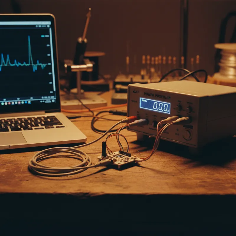
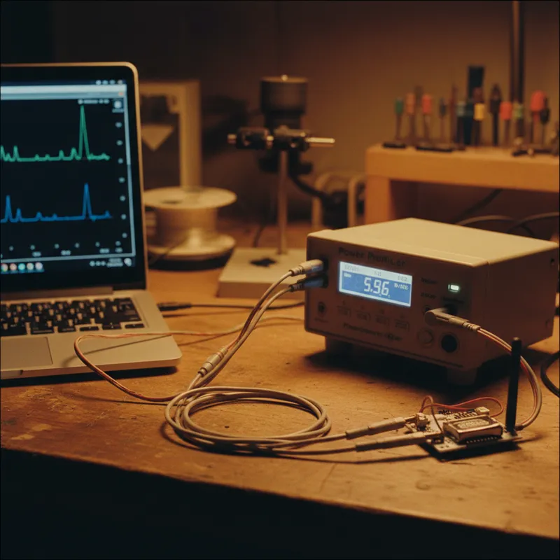
Battery life is consistently cited as the number one concern for IoT device manufacturers, yet many engineering teams rely on inadequate measurement techniques that miss the very power consumption anomalies that drain batteries prematurely. Conventional multimeters average out the rapid current transitions between sleep and active modes, while oscilloscope-based shunt measurements often lack the dynamic range to capture both microamp sleep currents and milliamp transmission bursts on the same measurement setup.

The Joulescope JS220 precision DC energy analyzer addresses these limitations with its 9-decade dynamic range spanning 10 nanoamps to 10 amps, capturing the full spectrum of IoT power behavior without range switching or measurement gaps. Its always-in-line design maintains accurate measurements across the entire current range simultaneously, revealing hidden current draws in sleep modes, unexpected peripheral wake-ups, and inefficient power state transitions that are invisible to less capable instruments.

Integrating Joulescope measurements into automated test workflows through its Python API enables teams to track power consumption trends across firmware versions, automatically flag regressions in sleep current, and validate battery life estimates against real measurement data. This data-driven approach to power optimization transforms battery life from an afterthought into a continuously monitored engineering metric.

Interested in Joulescope tools?

Talk to our application engineers for personalized tool recommendations.

Stay in the Loop

Get monthly compliance updates, product insights, and engineering best practices delivered to your inbox.

Related Articles

Master and slave roles on a 100BASE-T1 link: the master PHY times its transmitter from a local clock, the slave recovers the clock from the received signal, with the both-master and both-slave misconfigurations that leave the link down, from GSAS Micro Systems India
Automotive Ethernet Automotive & Mobility

100BASE-T1 Link Won't Come Up: A Vendor-Neutral Checklist

A 100BASE-T1 link that will not come up is almost never a mystery, but the answers on the web are written per silicon vendor and do not transfer. This is the ordered bring-up checklist that holds regardless of which PHY, switch or SoC you have: physical layer first, then the PHY over MDIO, then the master and slave pairing, then the causes of a link that comes up and drops. The standards and tooling claims trace to IEEE 802.3 task force records, the Linux ethtool and kernel documentation or published test material. Written by the GSAS Micro Systems engineering team in India.

29 Aug 2026 · 14 min read
Two test paths leaving the same device under test, one into a conformance suite that returns a passed report and one into a partner node that surfaces a field defect, showing why an ECU can clear a published suite and still fail in a vehicle, from GSAS Micro Systems India
Automotive Ethernet Automotive & Mobility

Automotive Ethernet Conformance: TC8 and Testing Above It

Summarising TC8 as a layer 1 to layer 4 suite is wrong in both directions. The public OPEN Alliance ECU test documents run from transmitter distortion up to a SOME/IP chapter with its own standardised test stub, and they contain exactly one time synchronisation test case. This is what those documents enumerate, chapter by chapter, what genuinely lives above their boundary, why a passing ECU can still fail against a partner node, and how much pre-compliance work a Tier-1 in India can honestly do in-house before a test house visit. Written by the GSAS Micro Systems engineering team in India.

29 Aug 2026 · 12 min read
Split panel diagram comparing one control message on a shared multidrop CAN bus with one sensor stream on a switched point to point Ethernet link, labelled shared bus arbitration, node, point to point link, switch, control message and sensor stream, from GSAS Micro Systems India
Automotive Ethernet Automotive & Mobility

CAN vs Automotive Ethernet: When to Use Each

CAN and automotive Ethernet answer different questions, so the useful comparison is a decision table rather than a winner. This guide from GSAS Micro Systems sets CAN and CAN FD figures from CAN in Automation next to the IEEE 802.3bw objectives for 100BASE-T1, covers arbitration against switch queues, cost and harness consequences, failure modes on both sides, and what changes on an India bench team's setup when a project adds Ethernet next to the CAN it already runs.

29 Aug 2026 · 14 min read