
The Coin Cell Reality
The CR2032 lithium coin cell is the default power source for a vast category of small IoT devices, BLE beacons, wireless sensors, smart labels, key finders, and medical wearables. Its appeal is obvious: compact form factor (20 mm diameter, 3.2 mm height), 3 V nominal voltage (compatible with most low-power ICs without a boost converter), and rated capacity of 210 to 240 mAh. At face value, this capacity is enough to power a BLE sensor for years.
But the rated capacity is a best-case number, measured under conditions that bear little resemblance to actual IoT device operation. The reality of coin cell performance in pulsed-load applications is more nuanced, and engineers who design to the rated capacity without understanding the derating factors are setting their products up for premature battery death.
Capacity Derating Under Pulsed Loads
A CR2032’s rated capacity (typically 225 mAh) is specified at a continuous discharge rate of 0.2 mA to a 2.0 V cutoff. At this gentle, constant load, the battery delivers its full capacity. But IoT devices do not draw a constant 0.2 mA. They draw nanoamps in sleep and milliamps or tens of milliamps during radio transmission, a pulsed load with a peak-to-average ratio of 1000:1 or more.
Coin cells have significant internal impedance, typically 10 to 30 ohms for a fresh CR2032, increasing to 50 to 100+ ohms as the cell ages. When the device draws a 15 mA pulse (typical for a BLE transmission), the terminal voltage drops by 150 to 450 mV due to the internal impedance. For a cell at 2.8 V (partially discharged), a 450 mV drop brings the terminal voltage to 2.35 V, perilously close to the 2.1 V minimum operating voltage of many BLE SoCs.
The practical consequence is that the device may stop functioning long before the battery’s rated capacity is exhausted. The battery still has milliamp-hours of charge remaining, but it cannot deliver the pulse current without dropping below the device’s minimum operating voltage. The usable capacity, the capacity at which the terminal voltage under pulse load stays above the minimum operating voltage, is significantly less than the rated capacity.
Measuring Coin Cell Behavior With Joulescope
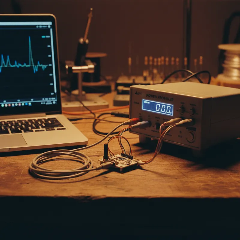
The Joulescope JS220 reveals the full picture of coin cell behavior under actual device load. Its simultaneous current and voltage measurement shows both the device’s current demand and the battery’s voltage response in real time.
Voltage Sag During Pulses
Connect the JS220 in series between the coin cell and the device. During a radio transmission pulse, the oscilloscope view shows the current rising to 10-15 mA while the voltage simultaneously dips by several hundred millivolts. As the cell ages and its internal impedance increases, these voltage sags deepen. The JS220 captures every sag with microsecond resolution, allowing the engineer to track voltage margin degradation over the battery’s lifetime.
End-of-Life Detection
The real end-of-life condition is not when the open-circuit voltage reaches the cutoff, it is when the voltage under pulse load drops below the device’s minimum operating voltage. The JS220’s simultaneous voltage measurement during pulse events pinpoints exactly when this occurs. By logging voltage and current over an extended discharge test, the engineer determines the actual usable capacity, the mAh consumed before the pulse voltage drops below threshold.
Temperature Effects
Coin cell internal impedance increases significantly at low temperatures. A CR2032 that delivers adequate pulse performance at 25 degrees C may fail at 0 degrees C because the increased impedance causes deeper voltage sags during transmission. For products deployed in cold environments (cold chain logistics, outdoor infrastructure monitoring in northern India), temperature-dependent discharge profiling is essential.
Conduct the same measurement at the minimum operating temperature and compare the usable capacity.
Optimizing Coin Cell Battery Life
Reduce Peak Current
Every milliamp of peak current reduction improves voltage margin under pulse load. Practical techniques:
- Lower transmit power: Reducing BLE transmit power from 0 dBm to -8 dBm can reduce peak current from 8 mA to 4.5 mA, halving the voltage sag. The range reduction is often acceptable for short-range applications (beacons, room-level sensors).
- Enable the DC-DC converter: Many BLE SoCs include an integrated DC-DC converter that reduces active current. For coin cell applications, verify that the DC-DC operates correctly at the battery’s end-of-life voltage.
- Stagger peripheral and radio activity: Do not read the sensor and transmit simultaneously. Complete the sensor read, process the data, then transmit. This avoids stacking sensor current on top of radio current.
Add a Buffer Capacitor
A 100 uF to 470 uF capacitor across the battery terminals provides local energy storage for pulse loads. During transmission, the capacitor supplies a portion of the pulse current, reducing the current drawn from the coin cell and reducing the voltage sag. The capacitor recharges from the coin cell during the sleep period between pulses.
The Joulescope measurement reveals the effectiveness of the buffer capacitor, measure the voltage sag with and without the capacitor to quantify the improvement. For some applications, a supercapacitor (1 to 10 F) provides enough buffering to support even cellular modem transmission bursts from a coin cell.
Choose the Right Battery Chemistry
Not all CR2032 cells are equal. Cells from different manufacturers have different internal impedance characteristics, different capacity at high discharge rates, and different temperature performance. Use the Joulescope to profile candidate cells from multiple manufacturers under your device’s actual load profile, and select the cell that provides the best combination of usable capacity, pulse voltage margin, and temperature performance.
For applications requiring more pulse current than a CR2032 can deliver, consider hybrid chemistries (lithium coin cell + supercapacitor), or move to a larger form factor (CR2450 with lower impedance, or AA lithium primary with much higher pulse capability).
Battery Life Estimation From Discharge Data
With the Joulescope discharge profile, battery life estimation becomes straightforward:
- Measure the usable capacity (mAh to the point where pulse voltage drops below minimum)
- Measure the average current (from the energy-per-cycle measurement)
- Divide: battery life = usable capacity / average current
This estimate is grounded in measurement, not assumptions. It accounts for the actual pulse load behavior, the actual usable capacity, and the actual device power consumption.
Why Buy Joulescope From GSAS
GSAS provides Joulescope instruments with INR invoicing and application support from offices in Bengaluru, Hyderabad, Chennai, Pune, Mumbai, and Delhi NCR. We help IoT product teams build measurement-based battery life validation processes that produce credible claims.
Contact sales@gsasindia.com or call +91 80 6590 1783.
Also appears in:
Interested in Joulescope tools?
Talk to our application engineers for personalized tool recommendations.
More from Joulescope
View all →
BLE Power Profiling: Measuring Bluetooth Low Energy Current With Joulescope
5 Apr · 7 min
Energy Harvesting and Power Measurement: Designing Self-Powered IoT Devices
5 Apr · 7 min

IoT Battery Life Testing: A Practical Methodology for Indian Product Teams
5 Apr · 7 min

IoT Power Consumption Trends: Why Indian Product Teams Need Better Measurement
5 Apr · 7 min

Emulating Processor Power for Thermal Testing: Why Constant Power
7 Oct · 7 min

CRPS and Rack Power Supply Testing: The Six Tests That Matter
7 Oct · 7 min


