
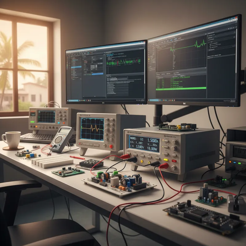
Programmable DC Electronic Loads for LED Driver Testing
India is one of the world’s largest LED lighting markets. The UJALA scheme alone distributed over 360 million LED bulbs, and Indian manufacturers now produce LED drivers for domestic consumption and export. Every LED driver, from a 3 W bulb driver to a 200 W street light driver, must be validated for output regulation, efficiency, dimming response, and protection circuit behaviour. The programmable DC electronic load is the primary instrument for this validation.
Why LED Drivers Need Specialised Load Testing
An LED is not a resistive load. Its forward voltage is relatively constant (typically 2.8 to 3.5 V per die), and above the threshold voltage, small voltage changes produce large current changes. An LED string of 10 series-connected dies presents approximately 30 to 35 V at rated current, but the dynamic impedance is only a few ohms.
This nonlinear characteristic creates specific challenges for driver testing.
Constant current mode is essential. LED drivers are current-regulated sources. The correct way to test an LED driver is to load it with a constant current sink and measure the output voltage, not the other way around. An electronic load operating in CC mode presents the correct impedance characteristic and allows you to sweep the load current from zero to rated output while monitoring voltage regulation.
Startup behaviour matters. Many LED drivers use soft-start circuits to limit inrush current to the output capacitor. The electronic load must respond correctly to the driver’s voltage ramp-up without triggering false overcurrent protection. Loads with programmable voltage limits (UV thresholds) prevent the load from attempting to sink current before the driver output has stabilised.
Dimming simulation. Dimmable LED drivers must be tested across their dimming range, typically 10% to 100% of rated current. PWM-dimmable drivers require the load to respond to rapidly switching current levels. Analogue-dimmable drivers require smooth current sweeps. The electronic load’s dynamic loading function and programmable sequences handle both scenarios.
Efficiency measurement. BIS standards and BEE star ratings for LED luminaires mandate minimum efficiency at rated load. Accurate efficiency measurement requires the electronic load to measure both voltage and current at the output with sufficient resolution. A 16-bit measurement system provides the 0.01% resolution needed for meaningful efficiency calculations at the 85% to 95% range typical of modern LED drivers.
GW Instek PEL-3000 Series for LED Driver Validation
Indian LED driver manufacturers evaluating electronic loads typically compare options from GW Instek, Prodigit, and Chroma. The GW Instek PEL-3000 series stands out for its combination of LED-specific test features and accessible pricing, backed by local GSAS application engineering and INR invoicing.
The PEL-3000 series is well-suited to LED driver testing across the power range common in Indian manufacturing.
PEL-3021 (150 W). Covers LED drivers up to 150 W, street lights, high-bay industrial luminaires, and decorative lighting. The 150 V / 15 A rating spans the voltage and current range of most single-string and multi-string LED configurations.
PEL-3031 (300 W). Addresses higher-power LED drivers for stadium lighting, industrial flood lights, and large-format signage. The wider operating area accommodates both low-voltage/high-current and high-voltage/low-current LED string topologies.
Features relevant to LED driver testing include programmable CC, CV, CR, and CP modes, dynamic loading with configurable frequency and duty cycle for PWM dimming simulation, voltage and current measurement with 16-bit resolution, programmable sequences for automated test routines (sweep current from 10% to 100% in defined steps, measure voltage and calculate efficiency at each point), and OCP/OVP test functions for protection circuit validation.
Production Test Integration
For Indian LED driver manufacturers running production lines, the PEL-3000’s remote control interfaces (USB, LAN, RS-232, GPIB) enable integration with automated test systems. A typical production test sequence for a 50 W LED driver takes less than 30 seconds.
- Connect DUT to electronic load and AC source
- Power on, load monitors output voltage rise (soft-start verification)
- Set CC mode at rated current, measure output voltage (regulation check)
Sweep current from 100% to 10% in 10 steps, measure voltage at each step (dimming range verification) 5. Measure input power and output power, calculate efficiency (BEE compliance) 6. Trigger OCP test, verify driver enters protection mode at 110% rated current 7.
Log results and pass/fail verdict
This sequence runs entirely under remote control, with the electronic load acting as both the loading element and the output measurement instrument.
Common Standards for LED Driver Testing in India
IS 16102 (Part 1 & 2). Performance requirements for LED luminaires, includes efficiency, power factor, and output current regulation under load variation.
IS 16103. Safety requirements for LED drivers, requires testing of output short-circuit protection, open-circuit voltage limiting, and overload behaviour, all of which require a programmable electronic load.
BEE Star Rating. Energy efficiency rating for LED luminaires, efficiency measurement at rated load is the primary metric.
Buy GW Instek PEL-3000 Electronic Loads in India from GSAS
GSAS Micro Systems provides GW Instek programmable electronic loads across India, with application support from our offices in Bengaluru, Hyderabad, Chennai, Pune, Mumbai, Delhi NCR, and Visakhapatnam. Whether you are setting up an LED driver validation lab or integrating electronic loads into a production test system, our test and measurement engineers can help you select the right configuration and develop automated test sequences.
Also appears in:
Interested in GW Instek tools?
Talk to our application engineers for personalized tool recommendations.
More from GW Instek
View all →
Emulating Processor Power for Thermal Testing: Why Constant Power
7 Oct · 7 min

CRPS and Rack Power Supply Testing: The Six Tests That Matter
7 Oct · 7 min

GPU Power Board Testing: DC Input Verification Before Integration
7 Oct · 6 min
Servo Motor Inrush Current Testing: Method, Limits and Bench
7 Oct · 6 min

SuperTest Van Gogh 6.0: C23, C++23 and the C++20 Modules Gap
6 Oct · 7 min

AI Inside the Engineering Process: What Is Worth Automating, and What Still Needs an Engineer
21 Sept · 11 min


