

Traditional in-circuit testing relies on physical probe access to individual nets on a circuit board. For decades, that approach worked, boards were large and test pads were plentiful. But modern ECU designs have moved in the opposite direction: components are smaller, boards are denser, and many ECUs ship encapsulated with no exposed test points. The traditional bed-of-nails fixture cannot reach what it needs to test.
ProMik’s SMART ICT (Intelligent Circuit Test) technology addresses this problem by reversing the direction of test access. Instead of probing the board from the outside in, SMART ICT tests it from the inside out, using the microcontroller already sitting on the board as the test instrument.
How SMART ICT Works
The concept is straightforward. SMART ICT downloads test software into the MCU through the programming interface, the same interface used during production flash programming. The MCU then executes test functions internally, exercising its own peripherals, measuring responses, and reporting results back through the programming interface.
This means the MCU itself becomes the test instrument. Every I/O pin, ADC channel, and communication interface that the MCU can access is also accessible to the SMART ICT test software, no bed of nails or test pads required. If the MCU can drive it or read it, SMART ICT can test it.
Peripheral and Controller Tests
SMART ICT divides its test capabilities into two categories: peripheral (external) tests and controller (internal) tests.
Peripheral tests exercise the devices and circuits connected to the MCU. These include testing peripheral devices via MCU I/Os and ADCs, interface tests across fieldbus and serial communication channels, memory tests covering Flash, RAM, and eMMC, sensor and actuator tests, and restbus simulation. Each of these tests uses the MCU’s own hardware peripherals to stimulate and measure the external circuit, the same way the circuit will operate in the field.
Controller tests focus on the MCU itself. These include MCU stress tests, interconnection tests (including for non-boundary-scan devices), built-in self-tests, and functional safety tests such as ECC error simulation. These internal tests verify that the MCU is operating correctly before it is trusted to test the surrounding circuitry.
Measurements and Additional Hardware
Beyond the MCU-driven tests, SMART ICT supports voltage level measurement and current consumption monitoring, including both run mode and sleep mode current profiles.
ProMik also provides a family of additional hardware modules that extend SMART ICT’s measurement capabilities beyond what the MCU alone can achieve:
- Power Control Current Sensor (PCCS): precision current sensing for power rail monitoring
- Galvanic Isolation Module: electrical isolation between test system and DUT
- Power Sequencer Box: controlled power supply sequencing for multi-rail boards
- Frequency Measurement Module: external frequency measurement
- Level Shifter: voltage level translation for mixed-voltage designs
- LIN Multiplexer: routing for LIN bus test channels
- Watchdog Trigger: external watchdog management during test
- PSU2048: a programmable power supply with four outputs, each delivering 4-50 V at up to 4 A (50 W per channel)
- Fuse Charge Pump: controlled fuse programming
These modules connect to the ProMik MSP2300net programming and test platform, forming a complete production test cell.
Why Inside-Out Testing Delivers Higher Coverage
The coverage advantage of SMART ICT over traditional ICT follows directly from its architecture. A traditional ICT fixture can only test nets that have physical test points, and on a modern ECU with BGA packages, shielded modules, and potted assemblies, many nets have no accessible test point at all. SMART ICT bypasses this limitation entirely. If a peripheral is connected to the MCU, it is testable, regardless of physical board access.
This matters particularly for encapsulated ECUs and boards with limited physical access, exactly the designs that are becoming standard in automotive, industrial, and aerospace applications. Where a traditional ICT fixture might achieve partial coverage due to inaccessible nets, SMART ICT tests the same circuits through the MCU’s own peripheral connections.
Relevance for Indian ECU Manufacturing
As ECU production volumes grow across India, driven by automotive electronics localization, EV powertrain development, and industrial automation, production test strategies must keep pace with board complexity. SMART ICT offers a path forward for manufacturers in Bengaluru, Pune, Chennai, and other electronics hubs who are building increasingly complex boards that resist traditional ICT approaches.
GSAS is the authorized ProMik engineering partner in India, providing the MSP2300net platform, SMART ICT modules, and production integration support. Teams working with encapsulated ECU designs or high-density boards where traditional ICT coverage falls short can evaluate SMART ICT as a production-ready alternative.
Also appears in:
Interested in ProMik tools?
Talk to our application engineers for personalized tool recommendations.
More from ProMik
View all →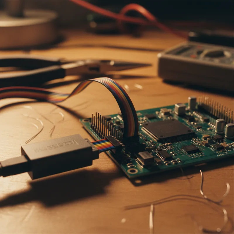
Automotive ECU Programming and Traceability: Meeting IATF 16949 with ProMik
5 Apr · 7 min

Scaling Electronics Manufacturing in India: Programming Infrastructure for Growth
5 Apr · 7 min

FlashTask Pro: Production Programming Project Management with ProMik
5 Apr · 7 min
Gang Programmer vs Inline ISP: Choosing the Right Production Programming Approach
5 Apr · 7 min

Emulating Processor Power for Thermal Testing: Why Constant Power
7 Oct · 7 min

CRPS and Rack Power Supply Testing: The Six Tests That Matter
7 Oct · 7 min


