
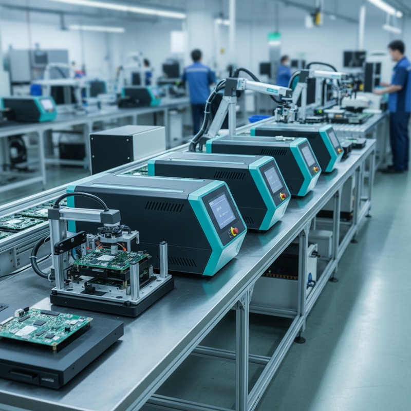
Production test floors in automotive electronics typically accumulate separate stations for flash programming, boundary scan, and functional test. Each station has its own hardware, its own software, its own fixture, and its own reporting pipeline. The result is a fragmented process where traceability gaps emerge between stages, cycle time bloats from manual handoffs, and every new product variant demands fixture rework across multiple stations.
ProMik’s SMART Test platform eliminates this fragmentation by combining all three disciplines, flash programming, boundary scan, and functional test, into a single standardized hardware platform.
One Hardware Platform, Multiple Disciplines
SMART Test Basic Hardware is a single standardized unit that serves as an all-in-one tool for Boundary Scan, Flashing, Functional Test, Powering, and Fieldbus Communication. The platform provides test interfaces across USB, Ethernet, FlexRay, CAN FD, and LIN, covering the full range of automotive bus protocols encountered in modern ECU production.
The hardware features configurable I/Os for various interfaces and an internal target power supply, meaning the test station is self-contained. No additional hardware sits inside the fixture or adapter. This is a one-time hardware investment that can be reused across multiple projects by reconfiguring the I/O mapping and test sequences in software.
The architectural difference from traditional setups, where boundary scan tools, programmers, and functional testers are separate instruments from separate vendors, is significant. Instead of managing three hardware platforms with three software environments, production engineers work with one software for all steps from flash to full functional test.
Production Cost and Cycle Time
The unified approach produces measurable benefits on the production floor:
- Lower production costs: one station replaces multiple setups, reducing equipment, floor space, and maintenance overhead
- Improved traceability: unified reporting and full process transparency from flash to test, no data gaps between stages
- Optimized cycle time: combining tasks into a single station enables faster processing and better resource efficiency
For high-volume production environments, automotive Tier-1 suppliers running thousands of ECUs per shift, the reduction from three sequential stations to one parallel station changes the throughput equation fundamentally.
Scalability and Test Coverage
SMART Test is designed for scalability and parallel testing. The platform easily adapts to different products and enables panel testing, where multiple PCBs on a production panel are programmed and tested simultaneously.
Test coverage improves as well. Integrated SMART ICT and Boundary Scan ensure thorough testing on complex PCBs, catching solder faults, open pins, and connectivity issues that standalone functional test alone would miss. The combination of structural test (boundary scan) with functional verification in a single pass provides higher coverage than either method in isolation.
This matters particularly for complex multilayer automotive PCBs where traditional in-circuit test access is limited by component density and board-level shielding.
End-of-Line Testing for Encapsulated ECUs
SMART Test extends beyond bare-board production into finished-unit validation with end-of-line testing capabilities:
- High-speed programming via USB and Automotive Ethernet
- Customization tasks: software upload, serial number writing, cybersecurity key injection
- Functional test of the completed ECU
- Interface and communication tests across all supported bus protocols
- Frequency and current tests for analog verification
- Diagnostic tests including UDS and DoIP protocols
- Restbus simulations for testing ECU behavior in simulated vehicle networks
A critical capability here is deep-level functional testing for encapsulated or boxed ECUs: units where no debug interface is accessible. Once an ECU is sealed in its production housing, traditional debug-based test methods are unavailable. SMART Test performs functional verification through the ECU’s production interfaces (CAN FD, LIN, Ethernet), enabling comprehensive end-of-line validation without requiring physical access to debug headers.
The Case Against Fragmented Test Infrastructure
The traditional approach, separate boundary scan tool, separate programmer, separate functional tester, made sense when each discipline required specialized hardware that could not be consolidated. That constraint no longer holds. Modern FPGA-based test platforms can handle the timing requirements of boundary scan, the protocol stacks for flash programming, and the signal conditioning for functional test within a single hardware architecture.
Organizations still running fragmented test infrastructure pay a recurring cost in fixture duplication, software license stacking, and traceability reconciliation between disconnected reporting systems. The unified platform approach removes these costs at the architectural level.
SMART Test Through GSAS in India
GSAS is the authorized engineering partner for ProMik in India, providing SMART Test platform sales, integration support, and technical training across Bengaluru, Hyderabad, Chennai, Pune, Mumbai, and Delhi NCR.
For automotive Tier-1 suppliers and EMS companies evaluating their production test infrastructure, the ProMik MSP2300net flash programming platform and the broader ProMik production solutions portfolio are available for evaluation through GSAS.
Also appears in:
Interested in ProMik tools?
Talk to our application engineers for personalized tool recommendations.
More from ProMik
View all →
Automotive ECU Programming and Traceability: Meeting IATF 16949 with ProMik
5 Apr · 7 min

Scaling Electronics Manufacturing in India: Programming Infrastructure for Growth
5 Apr · 7 min

FlashTask Pro: Production Programming Project Management with ProMik
5 Apr · 7 min
Gang Programmer vs Inline ISP: Choosing the Right Production Programming Approach
5 Apr · 7 min

Emulating Processor Power for Thermal Testing: Why Constant Power
7 Oct · 7 min

CRPS and Rack Power Supply Testing: The Six Tests That Matter
7 Oct · 7 min


