
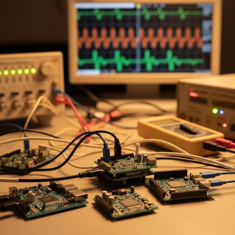
The Digilent Analog Discovery 3 is the kind of instrument that prompts scepticism on first encounter. A USB-powered device smaller than a smartphone that claims to replace an oscilloscope, logic analyzer, waveform generator, spectrum analyzer, network analyzer, pattern generator, power supply, voltmeter, and data logger, all for a fraction of the cost of any one of those instruments in benchtop form. The scepticism is understandable.
But the Analog Discovery 3 delivers on the claim, within specifications that are genuinely useful for the majority of embedded systems, mixed-signal, and IoT development work.
Part of the Digilent Discovery family, now under the Emerson/NI umbrella, the Analog Discovery 3 represents the third generation of a multi-instrument concept that has been refined through over a decade of deployment in university labs, engineering startups, and field service applications worldwide.
What You Get
2-channel oscilloscope. 125 MS/s sampling rate, 14-bit vertical resolution, +/- 25V input range. The 14-bit resolution is notable, most USB oscilloscopes and many benchtop scopes operate at 8-bit resolution, which limits the ability to resolve small signals riding on large DC offsets. The 125 MS/s bandwidth is adequate for signals up to approximately 30 MHz (following the Nyquist criterion with margin), covering UART, SPI, I2C, CAN, and many PWM and switching converter waveforms.
16-channel logic analyzer. 100 MS/s sampling rate on all channels simultaneously. Supports protocol decoding for SPI, I2C, UART, CAN, and custom protocols. For mixed-signal debugging, correlating analog and digital signals in the same time base, this capability eliminates the need for a separate logic analyzer.
2-channel waveform generator. 25 MHz output, 14-bit resolution. Sine, square, triangle, ramp, noise, DC, and arbitrary waveform modes. Useful for injecting test signals into circuits under development, clock signals, modulated waveforms, sensor stimulus signals.
Pattern generator. 16 digital output channels at up to 100 MS/s. Generates digital stimulus patterns for exercising digital inputs during testing.
Programmable power supply. Two channels, 0-5V programmable output. Sufficient for powering the device under test in many embedded systems applications.
Spectrum analyzer. FFT-based analysis from the oscilloscope channels. Not a dedicated spectrum analyzer, but adequate for identifying frequency components, harmonic content, and interference sources.
Network analyzer. Bode plot (magnitude and phase vs frequency) and impedance analysis using the waveform generator as stimulus and oscilloscope as response. Useful for characterising filter responses, amplifier gain, and component impedance.
The WaveForms Software
All instrument modes are controlled through Digilent’s WaveForms software, a desktop application that runs on Windows, macOS, and Linux. WaveForms provides the user interface for every instrument mode: oscilloscope display with cursors, triggers, and measurements; logic analyzer with protocol decoding; waveform generator with modulation and sweep; network analyzer with Bode plot display.
The software is mature, responsive, and included free with the hardware, no subscription, no per-seat licensing, no feature tiers. For Indian engineering teams accustomed to the per-seat licensing costs of professional test equipment software, this is a significant practical advantage.
WaveForms also provides an SDK and scripting interface (JavaScript, Python) for automated test sequences, enabling the Analog Discovery 3 to serve as a programmable test instrument in production test jigs and automated characterisation setups.
Where It Fits in the Indian Engineering Workflow
Embedded systems development. For teams in Bengaluru, Pune, Chennai, and Hyderabad developing IoT devices, industrial controllers, automotive ECU prototypes, and consumer electronics, the Analog Discovery 3 provides the measurement capability needed at the engineer’s desk, without booking time on shared benchtop instruments.
Field debugging. For field service and commissioning teams who need to diagnose problems on-site, at customer facilities, manufacturing floors, or installation sites, the Analog Discovery 3 fits in a laptop bag alongside the development laptop.
Startup and small-team labs. For hardware startups and small engineering teams where equipping every engineer with a full benchtop instrument set is cost-prohibitive, the Analog Discovery 3 provides professional measurement capability at a fraction of benchtop instrument cost.
Education and training. For university electronics labs and corporate training programmes, the Analog Discovery 3 enables every student or trainee to have their own complete instrument set, hands-on learning that shared benchtop equipment cannot provide at scale.
What It Does Not Replace
The Analog Discovery 3 has limitations that are inherent to its form factor and price point:
- Bandwidth. 30 MHz practical analog bandwidth is insufficient for high-speed digital (LVDS, DDR, USB 2.0+, Ethernet PHY) where GHz-range oscilloscopes are needed.
- Input range. +/- 25V covers most low-voltage embedded systems but not high-voltage applications (power electronics, motor drives, mains-referenced circuits).
- Channel count. Two analog channels and 16 digital channels. Complex systems with many simultaneous signals require more channels.
For these applications, benchtop instruments (including Digilent’s higher-end Analog Discovery Pro series or traditional oscilloscope brands) remain necessary. The Analog Discovery 3 is the instrument for 80% of daily measurement tasks at the embedded systems engineer’s desk.
Why Buy from GSAS
GSAS is an authorized partner in India, providing the Analog Discovery 3 and the full Digilent product line with INR invoicing, local stock, and technical support. Our team serves engineers and institutions across Bengaluru, Hyderabad, Chennai, Pune, Mumbai, Delhi NCR, and Visakhapatnam.
Also appears in:
Interested in Digilent tools?
Talk to our application engineers for personalized tool recommendations.
More from Digilent
View all →
Real-World SDR Applications: 5G Research, Satellites, IoT and ADS-B
28 Aug · 6 min
What Is Software Defined Radio (SDR)? A Practical Explainer for Indian Engineering Teams
19 Aug · 9 min
ZedBoard FPGA-in-the-Loop: HDL Verifier vs HDL Coder
5 Aug · 9 min
AI Data Centers in India: Test, Measurement & Memory Boom
4 Jun · 14 min

Emulating Processor Power for Thermal Testing: Why Constant Power
7 Oct · 7 min

CRPS and Rack Power Supply Testing: The Six Tests That Matter
7 Oct · 7 min


