In short
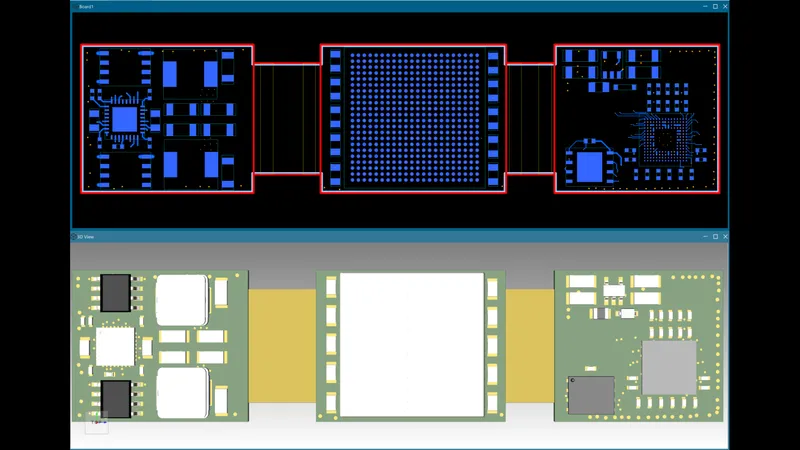
Per Siemens' edition checklist, rigid-flex design is included in Xpedition Advanced and Xpedition Enterprise and is an add-on in Xpedition Standard, where Siemens' token page lists it at 10 tokens. Siemens' Rigid-Flex Layout tutorial for Xpedition Advanced teaches the workflow in seven lessons: build a master stackup, define a stackup scheme for each board outline, create bend areas, place and route, add planes and cover lay, view the bends in 3D and review hazards.
Siemens introduced Xpedition Advanced with the Xpedition 2610 release, announced on 26 October 2026, and its edition checklist lists rigid-flex design as included in that edition. Every product statement below comes from Siemens’ “Rigid-Flex Layout” product introduction in the public Getting Started guide for Xpedition Advanced (a tutorial in seven lessons), the edition checklist, the Advanced page, the buyer’s guide and the token add-on pages, all linked under References.
This post follows the tutorial’s order and gives the reason for each step. A reason marked “general background” is ordinary flex engineering and says nothing about the product. Materials, bend-radius rules and fabrication limits are in our earlier post on flex and rigid-flex manufacturing challenges. Siemens’ full checklist is on our Xpedition family page, and the edition has its own Xpedition Advanced page.
Which Xpedition edition has rigid-flex design
The rows come from Siemens’ edition checklist. Add-on is Siemens’ word. “Included” stands for a tick or the word “included”, and “Not listed” for an empty cell or the word “none”.
| Checklist row (Siemens) | PADS Pro Essentials | Xpedition Standard | Xpedition Advanced | Xpedition Enterprise |
|---|---|---|---|---|
| Rigid-flex design | Not listed | Add-on | Included | Included |
| 3D design | Not listed | Included | Included | Included |
| ECAD-MCAD co-design - advanced | Not listed | Add-on | Included | Included |
In Xpedition Standard the add-on runs on tokens: Siemens’ token page lists “Rigid-Flex Design - 10 Tokens” and offers tokens in packs of 25 or 50. Siemens’ add-ons flyer describes that add-on with matching steps: master stackup, stackup schemes, bend controls, 3D flex-bend view and online hazard monitoring. To weigh the two routes, read Standard with tokens or Advanced and Xpedition Standard vs Xpedition Advanced.
Before you start
- Scope. Siemens says the tutorial “is not meant to be comprehensive training” and “covers only the electrical Layout portion” of a process that mechanical and electrical designers typically share.
- Lesson files. The designs are in ProductIntro.zip, in the examples folder of the installation. Each lesson opens its own prepared design.
- Access. The tutorial first checks Assistance > User Profile: “Rigid Flex” should show as acquired under Value Based Add-ons. The screenshot for that step shows an Xpedition Standard entitlement with the Rigid Flex add-on. Siemens’ Getting Started guide says that to reach capabilities such as “pre-/post-layout HyperLynx-powered SI” you also install “Xpedition Add Ons” from Siemens Software Center. It does not say whether rigid-flex is one of them. For blocked access, the guide says to “contact your ECA Admin to confirm license or credit assignment” (the ECA is your company’s Siemens Enterprise Cloud Account). Our getting started post covers installation.
- Design technology. On the Design tab of Settings, the lesson design is set to RigidFlex.
Step 1: Build the master stackup
General background: a rigid-flex board has more than one layer stack. The flex layers usually run through the rigid sections as inner layers, and the rigid sections add layers above and below them.
Siemens starts from a single list: “The master stackup is the combination of all stackup materials used within the design.” Each board outline later takes only its own materials from it.
The tutorial’s example has eight metal layers, SIGNAL_1 to SIGNAL_8. In the Stackup Editor (Settings > Design tab > Configure), the lesson adds the flex-only materials around SIGNAL_4 and SIGNAL_5: right-click a neighbouring layer, choose Insert Below or Insert Above, then Cover Layer or Adhesive. It names the four new layers Cover_Top, Adhesive_1, Adhesive_2 and Cover_Bot and enters a thickness for each. General background: cover lay (also written coverlay) is the flexible film that protects flex copper where a rigid board uses solder mask.
Step 2: Define stackup schemes
A scheme selects layers from the master stackup and assigns them to named board outlines. The tutorial’s board has three rigid outlines and two flex outlines, covered by two schemes.
| Scheme in Siemens’ tutorial | Board outlines | Layers taken from the master stackup |
|---|---|---|
| Rigid_1-8 | Rigid1, Rigid2, Rigid3 | All layers except Cover_Top, Adhesive_1, Adhesive_2 and Cover_Bot |
| Flex_4-5 | Flex1, Flex2 | Cover_Top, Adhesive_1, SIGNAL_4, POLY, SIGNAL_5, Adhesive_2, Cover_Bot |
Siemens shows two ways to assign a scheme. In Settings > Design tab > Stackup schemes, you name the scheme, then tick its board outlines and its layers. View Stackup shows the result, for viewing only. Or select an outline in the layout, open Properties and set its Type, Name and Stackup.
Why it matters, in Siemens’ words: “Layer Stackup definition controls the inner transitioning of routing between the rigid and flex board outlines.” Step 4 shows the effect on a part.
Step 3: Create bend areas
The command is Draw Create > Flex Objects > Draw Bend Area. The tutorial sets five of its properties (Board Outline, Bend Radius, Bend Angle, Bend Origin and Bend Order) and leaves the others at 0 or unticked. Per Siemens, “A bend area is created as a line and must start and end outside the board outline it belongs to.” Holding Shift snaps the line in 45-degree increments.
The tutorial puts two bend areas on each flex outline: one with radius 39.37 and angle 90, the other with radius 78.74 and angle 45, all with Bend Origin set to Center and Bend Order 1. These are Siemens’ example values. The Properties dialog in the tutorial labels the field “Bend Radius (th)”, the same th unit as its stackup thickness tables, and the values are not design guidance. General background: the minimum bend radius depends on the flex construction and on whether the bend is static or dynamic, so take yours from your fabricator.
The lesson then adds a 3D view and ticks Flex Bend on the 3D tab of Display Control: “You should now see the board flex with the bend areas you have defined.” Per Siemens, moving a bend area in the 2D view updates the 3D view automatically. The hazard checks in step 7 cover bend areas too.
Step 4: Place parts and route
Route border. Run Draw Create > Flex Objects > Generate Route Borders, select “Single route border for entire design” and enter a shrink value (the tutorial uses 15). Layout then places one route border inside all the board outlines.
Placement. The tutorial places part C27 on a rigid outline, then moves it to a flex outline. On the rigid outline its pads are on Layer 1. On the flex outline, per Siemens, they “are now on Layer 4 but are still on surface layer for the Flex Board Outline”, and the cover lay layer shows at the pads. Our reading: this is the Flex_4-5 scheme at work, because SIGNAL_4 is the top metal layer there. Siemens adds a library condition: cover lay pads appear only if the padstack is assigned to a top or bottom mount cover layer, under the Flex tab of the Padstack Editor.
Routing. Siemens says “Routing within the Flex environment is much the same as routing in a standard PCB” and adds that this holds in the transition area between rigid and flex board outlines too. The lesson plows a differential pair towards Flex1, presses 5 and then 4 to change layer and drop vias, and continues across to Flex1 and on to U5. Its caution: “make sure to always have Via Definition defined that contain the correct Via Spans.” General background: a via can connect only layers that exist where it is placed, and a flex section has fewer of them.
Step 5: Add planes and cover lay
Planes. In Plane Classes and Parameters, the tutorial shows a plane class named Flex Bend and opens its Hatch Options tab (width, distance, metal and patterns). Siemens’ reason: “Hatch can be used to help keep conductive planes from cracking within the bend areas.” You then draw the hatched plane shape on the flex outline.
Cover lay and adhesive. Per Siemens, “Draw Objects are also used when creating Cover Lay materials and the Adhesive used for bonding the Cover Lay.” The lesson copies the Flex1 outline as a draw object and sets its type to Adhesive on layer Adhesive_1. Mask Generator, under Manufacturing > Generator and Cleanup, then subtracts the cover layer pads from that shape: element A (adhesive graphics) minus element B (cover layer non-via pads), with optional grow or shrink. General background: pads that will be soldered must stay clear of cover lay and adhesive.
Step 6: View the board in 3D
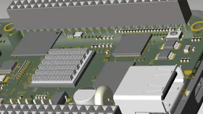
Integration > View > Add 3D View opens the 3D window. On the 3D tab of Display Control, Flex Bend shows the board flexed at its bend areas. Under Mechanicals > Appearance there are ticks for Enclosure and Visibility. Siemens’ add-ons flyer gives the purpose: “enable enclosure visibility for fit checks”.
For the exchange with mechanical CAD, Siemens’ checklist lists advanced ECAD-MCAD co-design as included in Advanced. Its add-ons flyer describes that capability, an add-on in Standard, as IDX-based and able to “Support rigid-flex transfer of bend areas and stackup changes”, and notes that full IDX 5.0 capability depends on MCAD support.
Step 7: Review hazards
Siemens says “additional rule features” for online DRC are available in the rigid-flex environment. They are in Hazard Explorer, on the top bar: “Available checks for Bend Areas and Board Outline > Invalid Flex Objects are found within Hazard Explorer.” The tutorial’s Hazard Explorer screenshot shows five checks under Bend Area (Invalid Bend Areas, Parts/Holes, Traces, Bend Violations and Plane Violations) and Invalid Flex Objects under Board Outlines. The tutorial does not explain what each check tests, so this post does not either.
Buying in India
GSAS Micro Systems is an authorized Siemens EDA partner in India. We supply Xpedition Standard with token-based add-ons, Xpedition Advanced, Xpedition Advanced DS (the schematic-only companion seat to Advanced) and Xpedition Enterprise. We do not publish prices for these products. We quote in INR with a GST invoice.
Tell us how many rigid and flex sections your board has, the layer count in each and how often you design rigid-flex, and we will say whether tokens on Standard or an Advanced seat fits. GSAS has offices in cities including Bengaluru, Hyderabad, Chennai, Pune, Mumbai and Delhi NCR. Request a quote or book a demo.
References
- Siemens: Getting Started guide for Xpedition Advanced, product introduction “Rigid-Flex Layout” (the seven lessons) and the installation notes
- Siemens: Xpedition product family, section “Choose the right PCB design solution for you” (edition checklist)
- Siemens: Xpedition Advanced (product page and FAQ)
- Siemens: Token-based add-ons for Xpedition (token packs and counts)
- Siemens: Scale Design Capabilities with Adaptable Add-Ons (rigid-flex and ECAD-MCAD add-on workflows)
- Siemens: Xpedition buyer’s guide (purchase options)
- Siemens EDA, Electronic Systems Design blog: What’s new in Xpedition 2610 (26 October 2026)
Also appears in:
Interested in Siemens EDA tools?
Talk to our application engineers for personalized tool recommendations.
More from Siemens EDA
View all →
PADS Pro Essentials vs Xpedition Standard: Which One to Start With
18 Nov · 8 min
Concurrent Schematic Design in Xpedition Advanced and Advanced DS
18 Nov · 7 min
From Layout to Fabrication in Xpedition Advanced: BluePrint, Panels, DFM
18 Nov · 10 min
Getting Started with Xpedition Advanced: An Onboarding Checklist
18 Nov · 8 min
High-Speed PCB Design in Xpedition Advanced: Constraints, Routing and SI
18 Nov · 9 min
Xpedition Advanced vs Xpedition Enterprise: Where Advanced Stops
18 Nov · 8 min