In short
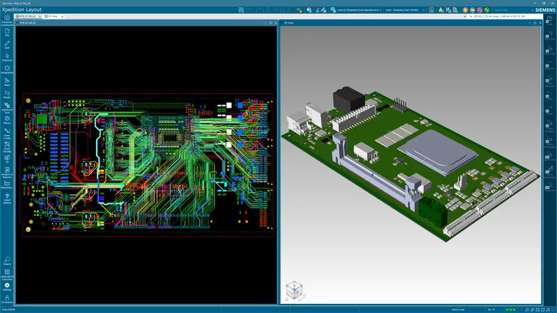
Per Siemens, Xpedition Advanced supports high-speed PCB design with extended electrical and physical constraints (for requirements such as time-of-flight delay, parallelism, crosstalk and topology), sketch planning with extended automated routing, and basic pre- and post-layout signal integrity simulation powered by HyperLynx. Full signal integrity simulation, power integrity simulation and the DDRx Wizard are listed by Siemens as options.
Siemens introduced Xpedition Advanced with the Xpedition 2610 release, announced on 26 October 2026, and describes it as “High-speed PCB design for growing teams with complex design constraints”. A high-speed board is designed in three steps: constrain the nets, plan and route against those constraints, then verify by simulation. Siemens lists a capability in Advanced for each step: extended electrical and physical constraints, sketch planning with extended automated routing, and basic signal integrity (SI) simulation powered by HyperLynx. Every product statement below comes from Siemens’ public Xpedition pages, the Advanced fact sheet and the Advanced Getting Started guide, all linked under References.
If you are comparing high-speed PCB design software, the full checklist is on our Xpedition family page, and the edition has its own Xpedition Advanced page.
Siemens’ buyer’s guide describes a typical Advanced buyer’s boards as having “more high-speed interfaces (DDR/PCIe/SerDes); constraint-driven design”. That line describes the buyer. The capabilities below come from the checklist and the product documents.
High-speed PCB design in three steps, by edition
The rows come from Siemens’ edition checklist. Core, Extended, Add-on and Option are Siemens’ words. “Included” stands for a tick or the word “included”, and “Not listed” for an empty cell or the word “none”.
| Step | Checklist row (Siemens) | PADS Pro Essentials | Xpedition Standard | Xpedition Advanced | Xpedition Enterprise |
|---|---|---|---|---|---|
| Constrain | Design constraints - schematic environment | Core | Core | Extended | Extended |
| Constrain | Design constraints - layout environment | Core | Core | Extended | Extended |
| Plan and route | Sketch planning | Not listed | Not listed | Included | Included |
| Plan and route | Automated routing | Not listed | Core | Extended | Extended |
| Plan and route | Concurrent team design - layout | Not listed | Not listed | Not listed | Included |
| Verify | Signal integrity simulation - basic | Not listed | Add-on | Included | Option |
| Verify | Signal integrity simulation - full | Not listed | Option | Option | Option |
| Verify | Power integrity simulation | Not listed | Option | Option | Option |
Advanced is the only column where basic SI simulation reads Included: Standard has it as a token add-on and Enterprise as an option. Siemens lists concurrent team layout for Enterprise only, so plan for one layout user per design in Advanced.
Step 1: Constrain
General background: once a trace’s delay is a significant fraction of the signal’s rise time, the trace behaves as a transmission line. Arrival time and coupled noise then depend on geometry and stack-up, which is why high-speed rules are written before routing starts.
Siemens’ Advanced page says the edition “provides extended electrical and physical constraints for requirements such as time-of-flight delay, parallelism, crosstalk and topology”. The checklist does not itemise which rule types are Core and which are Extended, so that sentence, which the fact sheet echoes, is the closest public statement of what Extended covers. Siemens’ “Advanced Logical Design” product introduction explains three of them.
- Time of flight. Controls arrival time, where a length rule controls only distance. Siemens’ reasoning: “Signal propagation speed varies with the stack-up, so two traces of equal length can arrive at different times if they travel on different layers.” Per Siemens, time-of-flight matching “helps ensure compliant timing regardless of the layers a signal traverses”.
- Parallelism rules. Control the geometry that causes coupling. Each rule defines pairings of net properties, together with “an acceptable separation distance and the maximum length the pair may run in parallel at that distance”. The two values are linked: closer traces are allowed less parallel length. Siemens says these rules are typically applied to the nets that carry the risk, such as clocks, strobes, reset lines and differential pairs.
- Crosstalk rules. Control the effect. Each rule “defines the maximum interference energy, measured in millivolts, that an aggressor net is permitted to induce on a victim net”. Siemens says a noise budget keeps the rule valid when the stack-up, trace width or dielectric changes, because Xpedition re-evaluates the coupled energy against the budget. Rules apply between nets or constraint classes and are not tied to a layer, so broadside coupling between adjacent layers is evaluated too. Violations are reported through the hazard explorer as routing progresses.
Topology, the fourth requirement Siemens names, is defined in Constraint Manager and covered in step 2.
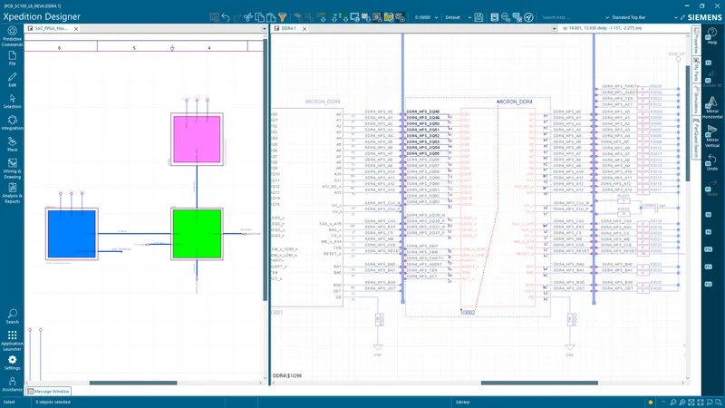
Constraint entry can be shared. Per Siemens, up to two schematic users can work at the same time, on different sheets (and constraints), with a third user in Layout through flow concurrency. Each user’s location is shown in the constraint spreadsheets. Our post on concurrent schematic design covers the setup.
Edition check. Constraints are Core in PADS Pro Essentials and Xpedition Standard, and Extended in Xpedition Advanced and Xpedition Enterprise, in both the schematic and the layout environment.
Step 2: Plan and route
Sketch planning
Siemens’ “Advanced Physical Design” product introduction sets out the trade-off. Routing hundreds of signals trace by trace gives full control and can take days or weeks, while an unconstrained autorouter finishes quickly and ignores design intent. Sketch planning divides the work: “The designer defines the topology, transmission line paths and layer strategy, while the sketch routing engine handles trace-packing, obstacle avoidance and rule enforcement.”
The workflow Siemens documents:
- Draw the plan. Select a group of nets (Siemens’ examples include signals in DDR byte lanes and a parallel bus) and draw one guide along the path. Per Siemens, “No copper is created at this stage”.
- Edit it freely. Plans are not physical objects, so constraints do not apply to them and they may overlap.
- Check the layer transitions. Where a plan changes layer, Xpedition generates a sketch via pattern that reserves space for the vias. You can toggle or rotate the pattern, and the solver marks an invalid one with an X.
- Read the width. Change a clearance in Constraint Manager, update the design, and the plans redraw at the new spacing. Siemens presents this as early feedback on whether a design can stay on four layers or needs six.
- Route in stages. Route the whole plan, a semi-trunk, the trunk only or the escapes only. Per Siemens, each pass is completed against the active rules.
Routing topologies and virtual pins
General background: the order in which a net’s loads are connected changes the delay each load sees. The product introduction lists five predefined topologies.
| Topology | What Siemens says it does |
|---|---|
| MST (minimum spanning tree) | Connects the pins using the shortest total netline length, without regard to signal order |
| Chained | A daisy chain: visits the pins in sequence, source first, then each load in turn |
| Star | Routes each load on its own branch from a common point |
| T-Shape | Splits the net at a virtual pin so that two branches of matched length run to their loads |
| H-Tree | Applies the same split recursively, so every load sits at the end of an electrically equivalent path |
Siemens describes a virtual pin as a routing guide that acts as a junction between the branches of a net. It has no pad and no copper of its own, and it gives the router and the length-matching engine a shared point at which the net divides.
Siemens gives two cautions. MST and Chained are not selectable for differential pairs. And changing the topology type on a net that already carries pin pairs, from-tos or virtual pins can delete those objects, so settle the topology before entering detailed constraints against the net.
For the router itself, the fact sheet says: “The advanced auto-router supports differential pairs, HDI vias, tuning, and other high-speed layout requirements.”
Edition check. Sketch planning is listed for Xpedition Advanced and Xpedition Enterprise only. Automated routing is Core in Xpedition Standard and Extended in Advanced and Enterprise.
Step 3: Verify
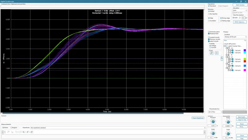
The rules in step 1 set limits. Simulation shows the waveform. Siemens’ Getting Started guide says Xpedition Advanced includes “pre-/post-layout HyperLynx-powered SI”, with one installation detail: you also install the “Xpedition Add Ons” entry in Siemens Software Center.
Two product introductions show what the workflows cover. Siemens says neither is comprehensive training.
| Aspect | Pre-layout | Post-layout |
|---|---|---|
| Input | Nets exported to HyperLynx LineSim from Xpedition Designer or Xpedition Layout | The routed board, opened in HyperLynx from Xpedition Layout |
| Models | Buffer models assigned per pin in the Assign Models dialog | IBIS models assigned by reference designator |
| What the tutorial does | Reviews the stack-up and impedance planning, runs the Terminator Wizard, couples transmission lines to simulate crosstalk, sweeps trace width and a resistor value | Probes a net on the virtual oscilloscope, then runs the General SI Batch Wizard across a set of nets and opens the HTML report |
Pre-layout work answers questions while the design is still cheap to change: which termination, which trace width and separation for the target impedance, how much a neighbour couples.
Post-layout work checks the board as routed. The batch wizard in the tutorial has options for signal quality (overshoot, ringback, monotonicity), delay and crosstalk. The crosstalk threshold is entered in millivolts, the same unit as the crosstalk rule in step 1. The 150 mV the tutorial enters is an example value, not a recommendation.
Edition check. Basic SI simulation is Included in Xpedition Advanced. In Xpedition Standard it is a token add-on: Siemens publishes 15 tokens for pre-layout SI and 25 for post-layout SI. In Xpedition Enterprise the checklist lists it as an option. If you are weighing the token route, see Standard with tokens or Advanced.
What stays an option
The checklist lists full SI simulation as an option and does not define where basic ends and full begins. The fact sheet names what else sits outside the included set: “additional options include DDRx Wizard, integrated multi-discipline verification, intelligent design optimization, power integrity simulation, electrical rule checks, and schematic analysis”.
So do not assume the DDRx Wizard or power integrity simulation comes with the included simulation: Siemens lists both as options. HyperLynx is the product behind those options, and our HyperLynx SI/PI guide covers it. Our earlier post on DDR5 PCB design, written before Xpedition Advanced was introduced, covers the interface itself.
Buying in India
GSAS Micro Systems is an authorized Siemens EDA partner in India. We supply Xpedition Standard with token-based add-ons, Xpedition Advanced, Xpedition Advanced DS (the schematic-only companion seat to Advanced), Xpedition Enterprise and HyperLynx. We do not publish prices for these products: GSAS quotes in INR with a GST invoice.
Tell us the interfaces on your next board, the layer count and who runs the simulation, and we will say which edition and options fit. GSAS has offices in cities including Bengaluru, Hyderabad, Chennai, Pune, Mumbai and Delhi NCR. Request a quote or book a demo. If you are still choosing an edition, read our four-edition chooser.
References
- Siemens: Xpedition Advanced (product page and FAQ)
- Siemens: Xpedition Advanced fact sheet (routing, analysis options)
- Siemens: Xpedition product family, section “Choose the right PCB design solution for you” (edition checklist)
- Siemens: Getting Started guide for Xpedition Advanced, product introductions “Advanced Logical Design”, “Advanced Physical Design”, “Pre-Layout SI Analysis” and “Post-Layout SI Analysis”
- Siemens: Xpedition buyer’s guide (fit table)
- Siemens: Token-based add-ons for Xpedition (token counts)
- Siemens EDA, Electronic Systems Design blog: What’s new in Xpedition 2610 (26 October 2026)
Also appears in:
Interested in Siemens EDA tools?
Talk to our application engineers for personalized tool recommendations.
More from Siemens EDA
View all →
PADS Pro Essentials vs Xpedition Standard: Which One to Start With
18 Nov · 8 min
Concurrent Schematic Design in Xpedition Advanced and Advanced DS
18 Nov · 7 min
From Layout to Fabrication in Xpedition Advanced: BluePrint, Panels, DFM
18 Nov · 10 min
Getting Started with Xpedition Advanced: An Onboarding Checklist
18 Nov · 8 min
Rigid-Flex PCB Design in Xpedition Advanced: Stackups, Bend Areas and 3D
18 Nov · 8 min
Xpedition Advanced vs Xpedition Enterprise: Where Advanced Stops
18 Nov · 8 min