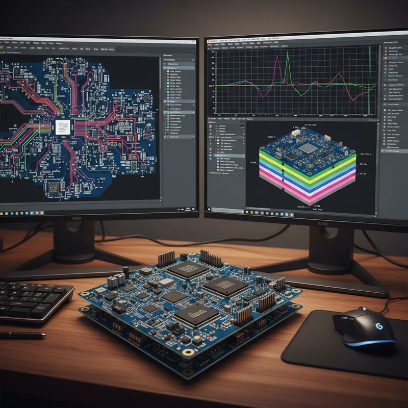
In most Indian product companies, two engineers sit a few desks apart and work on the same product without ever looking at the same model. The PCB designer works in Xpedition, placing components, routing traces, running DRC. The mechanical designer works in NX, SOLIDWORKS, or Creo, modelling the enclosure, defining mounting bosses, routing cable channels, simulating thermal paths. Each sees a different slice of the same physical object. They synchronise through email, shared folders, or a weekly review meeting where someone exports a STEP file and someone else imports it.
This works until it does not. The board outline in ECAD does not match the enclosure pocket in MCAD because someone changed a fillet radius and forgot to re-export. A 12 mm electrolytic capacitor collides with the enclosure lid because the mechanical model was using a 2D bounding box, not the actual component height. A connector cutout in the enclosure wall is 0.8 mm off from the connector footprint on the PCB because the mechanical engineer moved it to clear a draft angle, and the change never made it back to the layout tool.
These are not hypothetical failures. They are the kind of problems that surface at the first prototype review, force a board re-spin or an enclosure tool rework, and add weeks to the schedule. ECAD-MCAD collaboration, the practice of establishing a bidirectional, structured data link between the PCB design tool and the mechanical design tool, exists to eliminate this class of problem.
This article covers how ECAD-MCAD collaboration works with Siemens EDA (formerly Mentor Graphics) Xpedition, what exchange formats are available, how the integration differs depending on which MCAD tool your team uses, and where it delivers the most value for Indian product design teams.
The Problem: Parallel Design with No Shared Model
The core issue is structural. ECAD tools work with netlists, footprints, layer stackups, and design rules. MCAD tools work with solid bodies, assemblies, constraints, and tolerances. Neither tool natively understands the other’s representation of the same physical object.
Most Indian engineering teams bridge this gap through manual file exchange, DXF board outlines emailed to the mechanical team, connector positions in spreadsheets, component heights tracked in shared documents. This workflow has three failure modes that recur regardless of company size:
Stale data. The MCAD model reflects board outline revision 3, but the PCB layout is on revision 7. Incremental changes, a mounting hole shifted 2 mm, a board edge notch added, were never re-exported. By the time the discrepancy surfaces, the enclosure tool is already cut.
Incomplete data. A DXF board outline carries geometry but not component heights, keepout zones, or placement constraints. The enclosure fits the outline but violates height restrictions the mechanical designer never received.
One-directional flow. Data flows from ECAD to MCAD, but changes in the opposite direction, enclosure modifications that affect the PCB layout, are communicated informally or not at all.
ECAD-MCAD collaboration replaces this ad hoc process with a structured, bidirectional exchange that keeps both models synchronised through the entire design cycle.
Exchange Formats: IDF, IDX, STEP, and Native Integration
Not all ECAD-MCAD exchange mechanisms are equivalent. The choice of format determines what data can be exchanged, whether the exchange is incremental or full-replacement, and whether the workflow supports bidirectional negotiation. Xpedition supports all four major approaches.
| Format | Full Name | Data Richness | Incremental Updates | Bidirectional Negotiation | MCAD Tool Support |
|---|---|---|---|---|---|
| IDF 3.0 / 4.0 | Intermediate Data Format | Board outline, component placement, heights, keepouts | No, full board re-export each time | No, one-directional push | Nearly universal (NX, SOLIDWORKS, Creo, Inventor, Fusion 360) |
| IDX (IPC-2581) | Incremental Design Exchange | Board outline, placement, heights, keepouts, thermal zones, flex regions, design intent | Yes, sends only changed elements | Yes, propose/review/accept workflow | NX (native), SOLIDWORKS, Creo, Fusion 360 (via plugins) |
| STEP AP214/AP242 | Standard for the Exchange of Product Data | Pure 3D geometry (solids, surfaces) | No, full model re-export | No, geometry only, no design intent | Universal (any MCAD tool that reads STEP) |
| Native (Xpedition-NX) | Siemens internal integration | Full data model, geometry, constraints, design intent, change history | Yes, real-time incremental sync | Yes, integrated cross-probe and change proposals | Siemens NX only |
IDF is the legacy format, universally supported since the 1990s. It exports the entire board state every time, no concept of incremental updates. Re-importing a full IDF file risks overwriting MCAD-side modifications. Adequate for a one-time handoff. Poorly suited to iterative co-design.
IDX is the modern standard, co-developed by Siemens and ProSTEP iViP. It carries richer data than IDF, keepout zones, height restrictions, thermal pad areas, flex-bend regions, and supports incremental exchange. Only the changed elements are communicated. The mechanical designer reviews proposed changes, accepts or rejects each one, and can send counter-proposals back. This propose-review-accept protocol makes iterative co-design practical.
STEP is the universal 3D geometry format. It carries accurate solid-model geometry but no design intent, no keepouts, no height restrictions, no placement constraints. Useful for transferring a finished 3D board assembly for interference checking, but not a co-design format.
Native Xpedition-NX integration is the tightest link available. Both tools share a common Siemens data model. Enterprise-tier customers using Teamcenter PLM get managed, version-controlled exchange. Without Teamcenter, the native integration still provides tighter coupling than IDX, including real-time cross-probing between the 3D placement view in NX and the schematic/layout in Xpedition.
Xpedition and Siemens NX: The Native Integration Path
The deepest ECAD-MCAD collaboration Xpedition offers is with Siemens NX. This is not surprising, both are Siemens products, and the integration has been engineered at the platform level rather than through a file-exchange protocol.
With the native integration, the mechanical designer working in NX sees the PCB as a live, synchronised object, not a static import. Component placements update as the PCB designer moves parts. Board outline changes propagate in both directions. The mechanical designer can select a component in NX, cross-probe to Xpedition, and see it highlighted in the schematic and layout, useful for understanding why a component is placed where it is before proposing a mechanical change.
Keepout enforcement is automated. When the mechanical designer defines a volume in NX that the PCB must avoid, a structural rib, a cable channel, a boss for a neighbouring board, that volume appears as a keepout constraint in Xpedition. The PCB designer cannot place components in the restricted zone without explicitly overriding the constraint.
For teams using Xpedition Enterprise with Teamcenter, the integration extends to PLM-managed data exchange. Every ECAD-MCAD synchronisation event is version-controlled. Design reviews can trace the complete history of cross-domain changes, who proposed a board outline modification, who accepted it, what the rationale was. This level of traceability matters for regulated industries (medical devices, automotive safety systems, defence electronics) where design history files are a compliance requirement.
It is worth being precise about tier differences. Teamcenter PLM integration is an Xpedition Enterprise capability. Xpedition Standard supports ECAD-MCAD collaboration through IDX and IDF export/import and through token-based add-ons for enhanced co-design features, but the Teamcenter-managed workflow requires Enterprise.
Xpedition and SOLIDWORKS, Creo, and Fusion 360
Most Indian product companies do not use Siemens NX for mechanical design. SOLIDWORKS (Dassault Systemes) is the dominant MCAD tool in Indian SMBs and mid-tier OEMs. Creo (PTC) has a strong presence in automotive and industrial equipment. Fusion 360 (Autodesk) is increasingly common in startups and smaller hardware teams. This is the real-world multi-CAD landscape that ECAD-MCAD collaboration must accommodate.
Xpedition connects to these non-Siemens MCAD tools through IDX, IDF, and STEP, depending on what the MCAD tool supports and what level of integration the team needs.
Xpedition to SOLIDWORKS. The workflow is typically IDX-based. The PCB designer exports an IDX package containing board outline, component placements with 3D STEP models, keepout zones, and height restrictions. The SOLIDWORKS user imports via plugin or IDF/STEP import. Changes on the SOLIDWORKS side are exported back as IDX proposals. This works well for teams that establish a disciplined exchange cadence, but it is a round-trip cycle, export, import, review, modify, export back, taking minutes per cycle and requiring action on both sides.
Xpedition to Creo. The same IDX round-trip workflow applies. Creo’s ECAD-MCAD collaboration module supports IDX import and export with the propose-review-accept protocol. For Indian automotive Tier-1 suppliers standardised on Creo and adopting Xpedition for PCB design, this is the practical integration path.
Xpedition to Fusion 360. Fusion 360 supports IDF and STEP import for board geometry. The IDX workflow is less mature here, so teams typically work with a simpler exchange: STEP or IDF export from Xpedition, import into Fusion 360 for clearance checking, manual communication of changes back. For hardware startups in Bengaluru and Hyderabad using Fusion 360 with relatively simple enclosures, this is often sufficient.
The honest summary: the non-Siemens MCAD integration works, catches real problems, and prevents prototype rework. It is not as smooth as the native NX path. For most Indian product teams, “works with a disciplined round-trip” is a significant improvement over “manual DXF and email.”
3D STEP Component Models: Why They Matter
A PCB layout is inherently 2D, components are footprints on copper layers, traces are paths on stackup layers. But the physical board is a 3D object, and the most common ECAD-MCAD failures are 3D problems: a capacitor too tall for the enclosure, a connector extending beyond the board edge into a structural member, a heatsink blocking airflow.
Xpedition supports 3D STEP models attached to every component footprint. When a PCB designer places a 10 mm tall electrolytic capacitor, the 3D model carries the accurate height, body diameter, and lead geometry, not a rectangular bounding box. When the board assembly is exported to MCAD, the mechanical designer receives accurate component geometry enabling meaningful interference checking:
- Will the tallest component clear the enclosure lid with assembly tolerance?
- Does the USB connector body extend the correct amount for the enclosure cutout?
- Is there sufficient clearance between heatsink fins and the neighbouring capacitor bank?
- Will the battery connector mate without interference from board-mounted components?
Without 3D models, the MCAD side works with simplified bounding boxes that hide the interference problems that matter most in compact designs.
The practical implication for Indian teams: when setting up Xpedition, invest time in populating your component library with accurate 3D STEP models. Siemens provides the Valor Parts Library with 3D models for common components. For custom parts, models can be sourced from component manufacturer websites or created in-house.
The Incremental Change Protocol in Practice
In a real Indian product development cycle, the PCB layout goes through multiple placement iterations, often ten or more, as the team refines component positions, adjusts routing, responds to simulation feedback, and accommodates mechanical changes.
If every exchange requires re-exporting the entire board and re-importing it on the MCAD side, the overhead becomes burdensome enough that teams stop doing it. They fall back to exchanging at milestones, after initial placement, after routing, before prototype release, and the gap between exchanges is where mechanical surprises hide.
IDX solves this with incremental change packets. After the initial full exchange, subsequent updates contain only the delta: the three components that moved, the board edge segment that changed, the new keepout zone. The MCAD tool applies the delta to its existing model without disturbing the rest of the assembly.
This makes frequent exchange practical. Teams can synchronise daily, or after every significant placement change, without full model re-imports. The more frequently they exchange, the earlier conflicts surface, and the smaller those conflicts are.
Incremental exchange also preserves MCAD-side work. A full IDF or STEP re-import can disrupt MCAD-side annotations, assembly constraints, or modifications tied to the previous board model. Incremental exchange modifies only the changed elements, leaving the rest of the MCAD assembly intact.
Indian Use Cases That Drive Adoption
ECAD-MCAD collaboration is not equally valuable across all product types. Its impact is directly proportional to the mechanical complexity of the product and the tightness of the enclosure. Here is where Indian product teams see the most return.
IoT and wearable product teams (Bengaluru, Hyderabad). The PCB outline is shaped to fit a custom enclosure defined by ergonomic requirements. Battery placement drives the board shape. Thermal pad locations must align precisely with heatsink features. Antenna keepout zones constrain both component placement and enclosure material. These products are so tightly coupled across ECAD and MCAD that designing them independently guarantees rework.
Automotive ECU teams (Pune). Tier-1 suppliers design ECUs that must fit mechanical envelopes defined by the vehicle manufacturer. Connector positions, vibration clearances, and thermal interface pad alignment are non-negotiable. The ECU either fits the vehicle integration requirements or it does not. ECAD-MCAD collaboration ensures these constraints are designed in, not tested in.
Medical device teams (Bengaluru, Hyderabad). IEC 60601 creepage and clearance requirements impose keepout zones around high-voltage PCB sections. These zones must be respected by both component placement (ECAD) and enclosure geometry (MCAD), a metallic enclosure feature protruding into a creepage zone is a compliance failure.
LED driver and lighting teams. The PCB serves as both electrical substrate and thermal management component. Thermal pad locations must align with heatsink contact areas in the MCAD model. A misalignment of 1-2 mm can create a thermal hotspot that degrades LED lifetime.
Defence rugged computing teams. Ruggedised enclosures under MIL-STD-810 requirements demand tight tolerances. Board-to-chassis grounding points, conformal coating clearances, and EMI gasket compression dimensions all depend on coordinated ECAD-MCAD geometry.
When ECAD-MCAD Collaboration Matters: and When It Does Not
Not every PCB design needs ECAD-MCAD collaboration infrastructure. Being honest about where the overhead is justified helps teams make practical decisions.
ECAD-MCAD collaboration delivers clear value when:
- The product uses a custom enclosure designed around the PCB (IoT devices, wearables, medical instruments, automotive ECUs)
- The enclosure has tight clearances, less than 5 mm between the tallest component and the enclosure lid
- Multiple boards share a single enclosure and must avoid interfering with each other
- Regulatory requirements impose keepout zones that cross the ECAD-MCAD boundary (creepage, EMI shielding)
- The product goes through frequent design iterations where the mechanical and electrical designs evolve in parallel
ECAD-MCAD collaboration adds overhead without proportionate value when:
- The PCB fits into an off-the-shelf enclosure with generous clearance (a standard DIN rail module, a commodity plastic box)
- The board is a simple single-layer or two-layer design with no height-constrained components
- The product has a fixed, unchanging mechanical design and the PCB is a drop-in replacement (maintenance redesign of an existing product)
- The team is a single engineer doing both ECAD and MCAD in the same room, informal coordination is sufficient
For most Indian product companies, the decision comes down to enclosure type. If your mechanical designer is creating a custom enclosure for the product, invest in ECAD-MCAD collaboration. If your product uses an off-the-shelf enclosure and the PCB just needs to fit inside it, a one-time STEP export for clearance checking is sufficient.
Getting Started with ECAD-MCAD Collaboration in India
GSAS Micro Systems is an authorized Siemens EDA engineering partner for India. We support Indian product teams in setting up ECAD-MCAD collaboration workflows across the range of MCAD tools, whether your mechanical team uses Siemens NX, SOLIDWORKS, Creo, or Fusion 360.
The practical starting point for most teams is Xpedition Standard with IDX export configured for their MCAD tool. Teams that need Teamcenter PLM integration and the native NX real-time link should evaluate Xpedition Enterprise. GSAS engineers run ECAD-MCAD integration workshops that walk your ECAD and MCAD designers through the exchange setup, the propose-review-accept workflow, and the 3D component model library setup, using your actual product designs, not generic demos.
GSAS supports teams across Bengaluru, Chennai, Hyderabad, Delhi NCR, Mumbai, and Pune: with local application engineers who understand the Indian product development landscape.
Further Reading
External resources:
- Siemens EDA ECAD-MCAD Collaboration, Siemens’ overview of Xpedition ECAD-MCAD co-design capabilities
- Siemens NX product family, NX-side documentation for the native Xpedition integration
GSAS resources:
- Siemens EDA Partner Page, full overview of Siemens EDA products available in India through GSAS
- Xpedition Standard, product details, key specs, and how to buy in India
- Xpedition Enterprise, enterprise-tier product details including Teamcenter PLM integration
- ECAD-MCAD Co-Design: Eliminating Late-Stage Mechanical Surprises, our earlier deep-dive on the cost of late-stage mechanical surprises and IDX 5.0
- Migrating to Siemens Xpedition: A Practical Roadmap for Indian Design Teams, migration planning for teams moving to Xpedition from other PCB tools
Also appears in:
Interested in Siemens EDA tools?
Talk to our application engineers for personalized tool recommendations.
More from Siemens EDA
View all →
India's EDA Moment: Why Design Tool Demand Is Growing, and the Engineering Careers It Creates
21 Sept · 9 min

AI and Complexity Are Redrawing EDA: Siemens on the Trillion-Transistor Era
13 Sept · 6 min

Calibre Vision AI: Bringing Order to DRC Debug at Advanced Nodes
24 Aug · 4 min

Siemens EDA EBS Expert Series: 6 Free PCB Design Webinars (Jul-Aug 2026)
20 Jul · 8 min

Emulating Processor Power for Thermal Testing: Why Constant Power
7 Oct · 7 min

CRPS and Rack Power Supply Testing: The Six Tests That Matter
7 Oct · 7 min