India is building power electronics at scale. Data-centre and telecom UPS, rooftop and utility solar inverters, EV chargers and on-board chargers, and industrial motor drives are all being designed, qualified and manufactured here in growing volume. Every one of those products has to be load-tested, and the load is where benchtop reality often diverges from the datasheet.
A real load is rarely a clean resistor. It is non-linear, it draws current in bursts shaped by rectifier front-ends, it can demand full power the instant a UPS or inverter switches on, and in production it has to be pushed to tens or even hundreds of kilowatts. Testing that behaviour with a DC-only or purely resistive load leaves gaps exactly where field failures happen.
The case for a true AC and DC electronic load
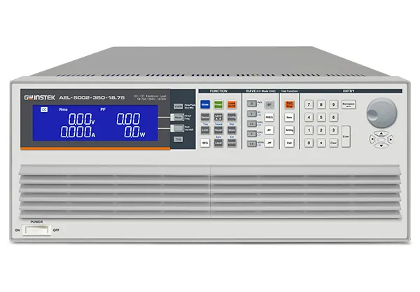
This is the problem the GW Instek AEL-5000 programmable AC/DC electronic load is built for. Unlike a DC-only load, it operates from DC and across 40 to 440 Hz (the 350 V and 425 V models; the 480 V models cover 40 to 70 Hz, see the product spec table for model-level detail), and it provides six loading modes: constant current (CC), Linear CC, constant resistance (CR), constant voltage (CV), constant power (CP) and a dedicated AC Rectifier Load Mode. Loading and unloading phase-angle control from 0 to 359 degrees lets engineers reproduce SCR/TRIAC waveforms and half-cycle stresses rather than an idealised sine.
The short product introduction below makes the headline point in under two minutes:
Load-on-at-startup: testing the moment a UPS or inverter wakes up
One capability the introduction calls out is load simulation with load-on at startup. By presetting the load-on state, the AEL-5000 begins drawing the set load current the instant the device under test powers up. When an inverter or UPS is switched on, it sees a real load immediately rather than ramping into a cold, open output. That single behaviour is essential for verifying transient stability, the case where a supply that looks fine into an open circuit becomes unstable the moment a real appliance is connected.
Scaling from the bench to 540 kW
The series spans 20 models from 1.875 kW to 22.5 kW per unit across the 350 V, 425 V and 480 V voltage ratings. When one chassis is not enough, up to eight units run in master-slave parallel: a single-phase array reaches 180 kW, and a synchronised three-phase array (Delta or Y) reaches 540 kW. A lab can start with a single unit for design validation and grow into a high-power production array without changing its test workflow.
For the cases that demand a brief surge rather than continuous high power, Turbo Mode lets the load draw twice its rated current and power within one second, which is how fuse and breaker trip tests, short-circuit simulation, and over-current and over-power protection verification get covered without sizing the load for that peak continuously. Over-voltage warning plus over-current, over-power and over-temperature protection guard the instrument across the range.
Non-linear efficiency testing for UPS and PV inverters
The AC Rectifier Load Mode reproduces the non-linear loading of switch-mode supplies and rectifier front-ends, simulating the real electronic equipment a UPS or PV inverter actually feeds. GW Instek specifies a Non-Linear mode for UPS efficiency measurement and a Resistive-plus-Non-Linear mode for PV-inverter efficiency measurement, so both efficiency tests run on one instrument instead of an assembled non-linear load bank. Optional GPIB, RS-232, USB and LAN interfaces bring all of this under automated test control.
Where it fits
The AEL-5000’s AC and DC loading, non-linear rectifier mode, Turbo Mode and parallel scalability suit it to:
- UPS testing: efficiency, back-up time and transfer-time measurement under realistic non-linear load.
- Inverter and PV-inverter testing: efficiency, transient response, inrush and surge verification.
- EV charger DC-output testing: as a DC electronic load up to 700 Vdc, the AEL-5000 can load the DC output of EV chargers and on-board chargers under automated control.
- Fuse and circuit-breaker qualification: trip and non-trip and short-circuit simulation with Turbo Mode.
- High-power production qualification: single-phase 180 kW and three-phase 540 kW parallel arrays on manufacturing lines.
It is a core instrument for EV and energy-systems and industrial automation test programmes. To complete a UPS or inverter bench, the AEL-5000 pairs with the GW Instek ASR-6500 programmable AC source.
Buy the GW Instek AEL-5000 in India
GSAS Micro Systems is an authorized engineering partner for Karnataka, Andhra Pradesh and Telangana, and supports GW Instek customers across the rest of India with service, calibration coordination and application integration. We supply the full AEL-5000 AC/DC electronic load range, all 20 models across 350 V, 425 V and 480 V ratings, with model selection and parallel-array sizing guidance, interface configuration, demonstrations, GST-compliant quotations, calibration with maintained traceability and post-sales application support. Power-electronics, UPS and inverter teams across Bengaluru, Hyderabad, Chennai, Pune, Mumbai and Delhi NCR rely on GSAS for fast access and local support. Contact GSAS or request a quote to get the AEL-5000 price in India and order with delivery nationwide.
Source: GW Instek AEL-5000 Series AC/DC Electronic Load product introduction (video). Specifications verified against the official GW Instek AEL-5000 product page and datasheet. Specifications are subject to change by the manufacturer without notice.
Also appears in:
Interested in GW Instek tools?
Talk to our application engineers for personalized tool recommendations.
More from GW Instek
View all →
Emulating Processor Power for Thermal Testing: Why Constant Power
7 Oct · 7 min

CRPS and Rack Power Supply Testing: The Six Tests That Matter
7 Oct · 7 min

GPU Power Board Testing: DC Input Verification Before Integration
7 Oct · 6 min
Servo Motor Inrush Current Testing: Method, Limits and Bench
7 Oct · 6 min

SuperTest Van Gogh 6.0: C23, C++23 and the C++20 Modules Gap
6 Oct · 7 min

AI Inside the Engineering Process: What Is Worth Automating, and What Still Needs an Engineer
21 Sept · 11 min