The Indian EV and Solar Power-Electronics Opportunity
The power electronics centre of gravity in India has shifted. Traction inverters for major Indian EV OEMs and newer platforms like TVS, Ola, Ather, and Exponent Energy are now being designed and validated in Bengaluru, Pune, and Chennai. Solar string and central inverters from Gujarat and Maharashtra compete on efficiency at the third decimal place. On-board chargers, DC-DC converters, motor drives, and BLDC pumps are all being redesigned to exploit SiC MOSFETs and, increasingly, GaN FETs: devices that switch faster, dissipate less, and ask a great deal more of the instruments that measure them.
The old-habit answer, drag an 8-bit benchtop scope out of the calibration room and hope, does not survive contact with a 650 V / 100 kHz SiC half-bridge. Eight bits of vertical resolution is a 0.4% least-significant-bit error on a 500 V bus, and that error hides the slow tail of the switching waveform exactly where the switching-loss integral lives. The measurement matters more than it used to, and the instrument that does it well matters more than it used to.
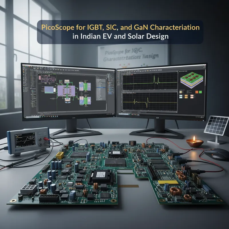
This post walks through the measurement setup for IGBT, SiC, and GaN dynamic characterization in Indian EV and solar contexts, and why the PicoScope 6000E FlexRes with 4444 differential inputs is the right bench instrument for the job.
Why IGBT, SiC, and GaN Are Measurement-Hard
IGBT: the workhorse of the first decade of Indian EV and solar inverters, switches in the 100 ns to 1 µs range with dv/dt in the low single-digit kV/µs. A 200 MHz scope captures it comfortably.
SiC MOSFET: now standard in Indian traction inverter design and in many 1500 V solar strings, switches in the 10 to 50 ns range with dv/dt in the 20 to 100 kV/µs range. The waveform has fast edges, overshoot ringing in the tens of MHz, and a slow settling tail that matters for switching-loss measurement. An 8-bit, 200 MHz benchtop scope misses most of the interesting detail.
GaN FET: increasingly used in on-board chargers (OBCs), DC-DC converters, and 48 V BLDC drives, switches even faster. Edges in the 1 to 10 ns range, dv/dt exceeding 100 kV/µs, and ringing in the tens to hundreds of MHz. The measurement bandwidth budget for GaN is a minimum of 500 MHz to avoid visibly distorting the edge.
For all three device classes, three things determine whether the measurement is usable:
- Enough bandwidth to capture the edge without distortion
- Enough vertical resolution to see the slow tail without drowning it in quantization noise
- Enough isolation on the high-side gate measurement to avoid killing the probe, the scope, or the engineer
The PicoScope 6000E FlexRes series, in combination with the 4444 differential inputs and a current measurement option, addresses all three.
Why PicoScope 6000E FlexRes
The PicoScope 6000E series ships across a range of bandwidth tiers from 300 MHz through 3 GHz (8-channel variants up to 1 GHz; the 6428E-D reaches 3 GHz on 4 channels). The FlexRes architecture lets the user trade sample rate for vertical resolution: run at 8 bits and maximum sample rate for edge capture, or run at 10 or 12 bits at lower sample rate for loss-integral and tail-of-the-switching-waveform work. For a double-pulse test, both modes matter, the rising edge wants the bandwidth, the Eoff integral wants the bits.
Deep capture memory is the other requirement. A double-pulse test captures perhaps 10 µs of data per pulse. To see the pulse edge at picosecond timing resolution and still hold the whole 10 µs window, the instrument needs hundreds of megasamples of memory. The 6000E’s memory depth is designed for exactly this.
For the deep-dive on the 6000E’s memory, sample-rate, and FlexRes design, see PicoScope 6000E deep dive.
Double-Pulse Test: The Canonical Characterization Workflow
The double-pulse test (DPT) is the canonical way to characterize a switching device’s dynamic behaviour. It is the starting point for every Indian traction inverter, solar DC-DC, and OBC design team doing SiC or GaN work.
Setup
A DPT fixture is a half-bridge with the DUT on the bottom, a high-side diode or synchronous MOSFET on top, and a load inductor across the output. The gate driver issues two pulses. The first pulse ramps the inductor current up to the target level. The off-time between pulses is short enough that the inductor current stays approximately constant. The second pulse is where the measurement happens, you capture the turn-on and turn-off transitions at a known device current and a known bus voltage.
What to Measure
- Vds: drain-source voltage across the DUT. Measured single-ended with a passive probe. The low side of a half-bridge is usually ground-referenced, so a passive probe is fine.
- Vgs: gate-source voltage of the DUT. Measured differentially because the source is not ground. The PicoScope 4444 is ideal for this, its galvanically isolated differential inputs remove the ground-loop error that a passive probe plus math channel would introduce.
- Id: drain current. Measured with a coaxial shunt (best fidelity, limited thermal capacity) or a current clamp (higher thermal capacity, lower bandwidth).
- Vgd or Miller plateau: derived from Vgs and Vds, useful for visualizing the Miller region.
The PicoScope 7 math channel multiplies Vds by Id to give instantaneous power. Integrate over the turn-off transition and you have Eoff; integrate over the turn-on and you have Eon. The sum scaled by switching frequency gives the total switching loss, the number Indian EV inverter and solar MPPT designers need for thermal sizing.
High-Side Gate Measurement: Differential Discipline
Measuring the high-side MOSFET gate of a 400 or 800 V SiC half-bridge is where single-ended scopes get engineers killed. The source of the high-side MOSFET is switching between 0 and the bus voltage at 50 kV/µs. A ground-referenced passive probe has no chance. You need a true differential measurement, either the PicoScope 4444 with the PicoConnect 442 attenuating differential probe (rated to 1000 V CAT III), or an external high-voltage differential probe feeding a single-ended scope input. The 4444 + PicoConnect 442 approach is usually simpler and more robust because there is one fewer failure mode.
Current Measurement: Rogowski, Clamp, or Shunt
The choice of current sensor matters as much as the voltage probe choice.
Coaxial shunt: A low-inductance coaxial resistor in the source return. Highest bandwidth, best fidelity for edge capture. Limited thermal mass, used for short pulses, not continuous operation. The right choice for DPT work.
Current clamp (Hall or CT): Clip-on, non-invasive, higher thermal capacity. Bandwidth limited (typically 50 to 100 MHz for high-quality clamps, less for low-end ones). The right choice for continuous inverter characterization and in-situ work on a running prototype.
Rogowski coil: Flexible loop you can thread around a busbar. Wide bandwidth, low insertion loss, integrates dI/dt internally. The right choice when the current path cannot be broken, e.g., a busbar in a packaged inverter or a production prototype.
Real-World Applications
3-Phase Traction Inverter Commissioning
A bench in Chennai or Bengaluru running up a new SiC traction inverter for a two- or four-wheel EV platform. Bus voltage 400 V, switching frequency 20 kHz, device ratings 1200 V / 200 A. The PicoScope 6000E captures the switching waveform at each phase, the 4444 measures differential gate voltages on the three high-side devices, and the math channel computes switching losses phase by phase. When a phase shows higher-than-expected Eoff, the engineer knows to look at gate-drive resistor, dead-time, or layout parasitics.
Solar MPPT DC-DC Efficiency Characterization
A solar R&D lab in Gujarat running up a new 1500 V string MPPT using SiC MOSFETs. Efficiency targets are specified to 0.1%. The PicoScope 6000E in FlexRes 12-bit mode captures the switching transitions with enough resolution to integrate the loss accurately. The 4444 captures phase-to-phase differential voltage on an interleaved topology.
On-Board Charger Characterization
An OBC design for a two-wheeler EV programme uses GaN FETs in the PFC front end and the LLC resonant stage. GaN demands 500 MHz of oscilloscope bandwidth to capture the switching edges without distortion. The 6000E at 500 MHz or 1 GHz handles this. The 4444 measures the differential resonant-stage voltages.
BLDC Drive Characterization for Industrial Pumps
Scenarios in this article are illustrative, common patterns Indian engineering teams encounter, not specific named customers.
A typical Pune-area-based industrial drive team characterizing a BLDC pump drive with IGBT-based six-step commutation. Lower device speed, 200 MHz scope bandwidth is fine, but the deep memory of the 6000E lets the engineer capture a full mechanical revolution of the motor (tens of milliseconds at full sample rate) without segmenting the memory.
For the data-logging and automation side of long-run battery characterization, see pyPicoSDK for EV battery characterization in India.
Instrument Recommendation
For a well-resourced traction-inverter R&D bench: PicoScope 6000E (1 GHz FlexRes or the 3 GHz 6428E-D) plus PicoScope 4444 for high-side differential gate work. Pair with a coaxial shunt for DPT and a precision current clamp for running-inverter work.
For a solar MPPT and DC-DC bench: PicoScope 6000E at 500 MHz is usually sufficient. The 4444 again for differential phase measurements.
For a production verification bench where a single instrument has to cover the whole power-electronics validation spread: PicoScope 6000E at 1 GHz plus the 4444, one bench that handles IGBT, SiC, and GaN without needing to re-equip for the next generation of devices.
For a demo at our Bengaluru, Pune, Hyderabad, Chennai, Mumbai, or Delhi NCR offices, see /partners/pico-technology.
Further Reading
- Pico Technology, PicoScope 6000E Series overview
- Pico Technology, Double-pulse test application notes (library)
- Pico Technology, PicoScope 4444 high-resolution differential oscilloscope
- GSAS, PicoScope 6000E deep dive
- GSAS, PicoScope power electronics, inverter, motor drive, and power supply analysis
- GSAS, pyPicoSDK for EV battery characterization in India
- GSAS, EV and energy systems solutions
- GSAS, Two-wheelers and EV solutions
- GSAS, Pico Technology partner page
Also appears in:
Interested in Pico Technology tools?
Talk to our application engineers for personalized tool recommendations.
More from Pico Technology
View all →
How to Buy an Oscilloscope in India (2026): USB vs Benchtop, Bit Depth, Bandwidth: A Buying Guide
5 Jun · 11 min
PicoScope 5000D vs 5000E: Native 16-Bit or FlexRes? A Buyer's Guide for Indian Labs
4 Jun · 11 min
PicoScope 5000E in India: The World's First 4-Channel 16-Bit USB Oscilloscope, Explained
4 Jun · 11 min
PicoScope 7 Goes Native Arm64: Apple Silicon, Snapdragon Windows and Arm Linux Test Benches in India
4 Jun · 11 min

Emulating Processor Power for Thermal Testing: Why Constant Power
7 Oct · 7 min

CRPS and Rack Power Supply Testing: The Six Tests That Matter
7 Oct · 7 min