
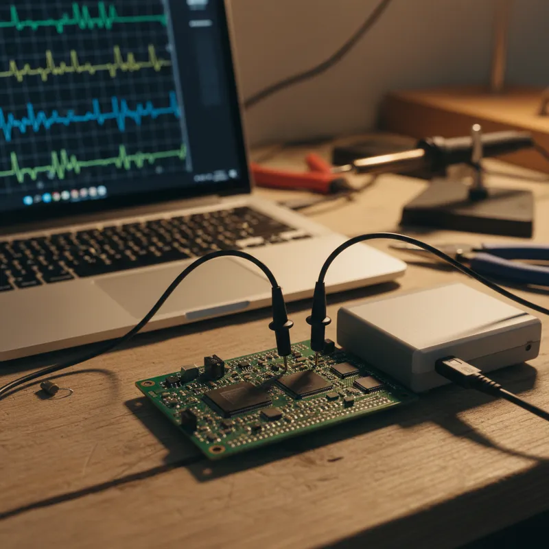
Power Electronics: Where Measurement Demands Are High
Power electronics, inverters, motor drives, DC-DC converters, battery management systems, solar inverters, EV chargers, presents some of the most demanding measurement challenges in electronics engineering. Voltages swing from 0 to 400V+ in nanoseconds. Currents change from zero to tens or hundreds of amps. Switching frequencies range from 10 kHz to 500 kHz. Ground references shift, common-mode voltages are high, and a measurement error can mean a false design validation or a safety risk.
PicoScope oscilloscopes, particularly the differential-input PicoScope 4444 and the high-bandwidth PicoScope 6000E, are purpose-suited for these measurements.
Differential Measurement: The Foundation
In power electronics, most signals of interest are not referenced to a common ground. Gate-source voltage of a high-side MOSFET, phase-to-phase motor voltage, and battery cell voltages all require differential measurement.
PicoScope 4444: Built for Differential
The PicoScope 4444 is a 4-channel oscilloscope with true differential inputs on all channels. Each input is galvanically isolated from the others and from the USB connection to the PC. This eliminates the ground loop problems that plague single-ended oscilloscopes in power electronics applications.
Key specifications for power measurement:
- Bandwidth: 20 MHz, sufficient for switching transient analysis up to approximately 200 kHz switching frequency
- Input range: ±1000 V peak differential (with appropriate probes)
- Isolation: 1000 V CAT III between channels and to ground
- Resolution: 12-bit native, important for measuring small ripple on large DC voltages
External Differential Probes
For higher bandwidth measurements (characterizing fast GaN or SiC switching transitions), PicoConnect 440 series differential probes provide up to 300 MHz bandwidth with high common-mode rejection. These probes connect to the standard BNC inputs of any PicoScope model.
Application: Inverter Switching Analysis
Switching Loss Measurement
Inverter efficiency depends critically on switching losses, the energy dissipated during each turn-on and turn-off transition. To measure switching loss:
- Measure VDS (drain-source voltage) across the switching device using a differential probe
- Measure ID (drain current) using a current probe (Rogowski coil or hall-effect clamp)
- Calculate instantaneous power: P(t) = V(t) x I(t) using PicoScope 7’s math channels
- Integrate power over the switching transition to obtain switching energy per event
- Multiply by switching frequency to obtain average switching power loss
PicoScope 7’s math channel capability handles steps 3–5 directly on the oscilloscope, without exporting data to external analysis tools.
Gate Drive Characterization
Gate drive waveforms determine how fast and cleanly the power device switches. Measure:
- Gate-source voltage: Rise time, fall time, plateau duration, and any oscillation or ringing
- Gate current: Quantifies the gate driver’s ability to charge and discharge the device’s input capacitance
- Miller plateau duration: Indicates the switching transition speed, shorter plateau means faster switching
The PicoScope 4444’s differential inputs allow simultaneous measurement of high-side and low-side gate drives without ground reference conflicts.
Application: Motor Drive Analysis
Three-Phase PWM Measurement
Motor drives generate three-phase PWM output to control motor speed and torque. Measuring all three phases simultaneously requires a minimum of three differential channels, the PicoScope 4444 provides exactly four.
Capture the three PWM phase voltages and the DC bus current to analyse:
- PWM duty cycle and modulation index
- Dead-time verification between high-side and low-side switching
- Harmonic content using PicoScope 7’s FFT spectrum mode
- Phase symmetry: ensuring balanced output across all three phases
Current Measurement
Motor phase currents are measured using current probes (Rogowski coils for high-frequency accuracy, or hall-effect clamps for DC and low-frequency). PicoScope supports current probe scaling, enter the probe’s sensitivity (mV/A) and the oscilloscope reads directly in amperes.
Application: DC-DC Converter Validation
For power supply designers in India’s growing EV and industrial electronics sectors, concentrated in Bengaluru, Pune, Chennai, and Hyderabad: DC-DC converter validation requires:
- Output voltage ripple measurement: Use FlexRes mode (12-bit) on the PicoScope 6000E for high-resolution ripple measurement on DC rails. AC-couple the input to zoom in on the ripple component.
- Transient response: Apply a load step and capture the output voltage recovery, overshoot, undershoot, and settling time
- Input current profiling: Measure input current waveform to characterize conducted EMI and input filter requirements
- Efficiency measurement: Simultaneous input voltage, input current, output voltage, and output current measurement, four channels, four probes, real-time power calculation
Why PicoScope for Power Electronics
The combination of differential inputs (PicoScope 4444), high bandwidth and deep memory (PicoScope 6000E), and math channels for real-time power calculation makes PicoScope a practical choice for power electronics labs. The total cost, scope, probes, and software with all protocol decoders included, is significantly below equivalent benchtop solutions.
Why Buy PicoScope from GSAS
GSAS Micro Systems is an authorized Pico Technology partner. We provide PicoScope oscilloscopes, differential probes, current probes, and application engineering support for power electronics teams.
- Probe selection and configuration for your specific voltage and current ranges
- Demo units at offices in Bengaluru, Hyderabad, Chennai, Pune, Mumbai, and Delhi NCR
- INR invoicing with GST-compliant documentation
- PicoSDK support for automated power electronics test systems
Also appears in:
Interested in Pico Technology tools?
Talk to our application engineers for personalized tool recommendations.
More from Pico Technology
View all →
How to Buy an Oscilloscope in India (2026): USB vs Benchtop, Bit Depth, Bandwidth: A Buying Guide
5 Jun · 11 min
PicoScope 5000D vs 5000E: Native 16-Bit or FlexRes? A Buyer's Guide for Indian Labs
4 Jun · 11 min
PicoScope 5000E in India: The World's First 4-Channel 16-Bit USB Oscilloscope, Explained
4 Jun · 11 min
PicoScope 7 Goes Native Arm64: Apple Silicon, Snapdragon Windows and Arm Linux Test Benches in India
4 Jun · 11 min

Emulating Processor Power for Thermal Testing: Why Constant Power
7 Oct · 7 min

CRPS and Rack Power Supply Testing: The Six Tests That Matter
7 Oct · 7 min


