

A hardware watchdog timer resets the system when firmware stops responding. In bare-metal, the approach is simple: feed the watchdog from the main loop. If execution stalls, the timer expires and forces a reset. This breaks in an RTOS.
In a multi-task environment, the main loop is replaced by a scheduler running independent tasks. A single task can hang, deadlocked on a semaphore, stuck in a retry loop, starved by a higher-priority task, while other tasks continue normally. If the watchdog is fed from any task that is still alive, the hung task goes undetected.
The Single-Loop Feeding Problem
Consider four tasks: sensor acquisition, communication, motor control, and a watchdog feeder. The feeder runs at the lowest priority and kicks the hardware watchdog every 500 ms. If the motor control task deadlocks, the feeder still runs, the watchdog never expires, and the motor sits in whatever state it was in when the task hung. In safety-critical applications, automotive ECUs, industrial controllers, medical devices, this failure mode is unacceptable.
The root cause: the watchdog feeder has no visibility into individual task health. It cannot distinguish between “all tasks are running” and “at least one task is running.”
embOS Watchdog Module
SEGGER embOS includes a watchdog supervision module that solves this at the RTOS level. Each task registers itself with the module and declares its own timeout. The module tracks every registered task independently and only feeds the hardware watchdog when all tasks have reported in within their deadlines.
-
Task registration: Each task calls a registration function with a custom timeout. A sensor task polling at 100 ms might register with a 300 ms timeout; a communication task handling slow network operations might use 2000 ms.
-
Periodic signaling: Each registered task calls a signaling API to indicate it is alive and making progress. This call goes at a point where forward progress is guaranteed, after completing a processing cycle, not merely at the top of the loop.
-
Health verification: A dedicated watchdog task or ISR iterates through all registered tasks and verifies each has signaled within its timeout window. Only if all tasks pass does it feed the hardware watchdog.
-
Malfunction handling: If any task misses its deadline, the hardware watchdog starves. The module can also invoke a custom malfunction handler, allowing the system to log which task failed, save diagnostic state to non-volatile memory, or attempt controlled actuator shutdown.
Running from Task vs ISR
The health check can run from either a dedicated task or a hardware timer ISR. Running from a task is simpler and permits RTOS API calls (e.g., logging via RTT). Running from an ISR provides extra protection: if the scheduler itself fails, the ISR still executes and the watchdog expires. For highest reliability, use a timer ISR independent of the RTOS tick.
Integration with SystemView
Watchdog events, registration, signaling, health check pass/fail, can be instrumented as SystemView custom events. This gives a timeline view of watchdog activity alongside task scheduling, making it easy to spot tasks approaching their timeout limits under heavy load before an actual failure occurs.
Practical Considerations
Place the signaling call where it proves forward progress, not merely execution. A task spinning in a retry loop without completing work should not signal the watchdog. The signal should come after meaningful work, after processing a reading, transmitting a message, or completing a control iteration.
For tasks that block on external events, structure the timeout to account for maximum expected blocking time plus margin. Alternatively, split the task so the blocking portion is separate from time-critical processing, and only supervise the processing portion.
Deploying embOS Watchdog Solutions in India
GSAS Micro Systems provides the full SEGGER embOS RTOS with the watchdog module, plus Ozone for debugging, SystemView for profiling, and Embedded Studio for development. Teams across Bengaluru, Hyderabad, Chennai, Pune, Mumbai, and Delhi NCR can access local application engineering support for integrating watchdog supervision into RTOS projects.
Also appears in:
Interested in SEGGER tools?
Talk to our application engineers for personalized tool recommendations.
More from SEGGER
View all →
Meet the GSAS Team at electronica India 2026, Stall H3.I45
15 Sept · 3 min
J-Link Is Now Validated by ST for StellarStudio
13 Sept · 2 min

An AI Agent That Drives the Debugger: SEGGER and Embedder Connect J-Link to the Loop
13 Sept · 6 min
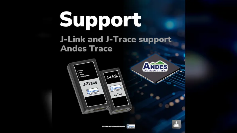
SEGGER J-Link and J-Trace Now Support Andes Trace: Why This Matters for RISC-V
21 Jul · 6 min

Emulating Processor Power for Thermal Testing: Why Constant Power
7 Oct · 7 min

CRPS and Rack Power Supply Testing: The Six Tests That Matter
7 Oct · 7 min

