
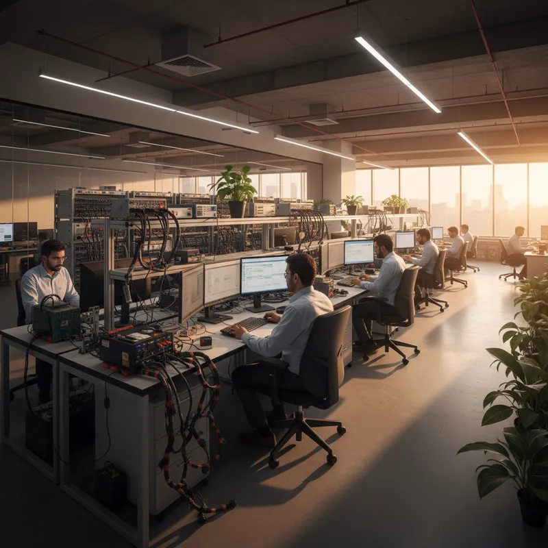
OBD-II in the Indian Context
On-Board Diagnostics II (OBD-II) is the standardised vehicle diagnostic interface mandated across passenger vehicles and light commercial vehicles worldwide. In India, OBD-II compliance became mandatory with BS-IV emission norms (April 2017) for passenger vehicles and has expanded under BS-VI (April 2020) to cover a broader range of vehicle categories with stricter monitoring requirements.
Every BS-IV and BS-VI compliant vehicle in India has an OBD-II port, a 16-pin Type A connector, typically located under the dashboard near the steering column. This port provides access to the vehicle’s Engine Control Unit (ECU) for reading diagnostic trouble codes (DTCs), real-time parameter data, freeze frame data, and emission readiness monitors.
OBD-II Communication Protocols
The OBD-II standard supports five communication protocols. Indian vehicles primarily use two:
- CAN (ISO 15765): mandatory for BS-VI vehicles, used by most manufacturers since BS-IV. Operates at 500 kbps on the high-speed bus. This is the protocol you will encounter on modern Indian vehicles from Maruti Suzuki, Toyota, Honda, and other major OEMs operating in India.
- ISO 14230-4 KWP (Keyword Protocol 2000): used by some older BS-III and early BS-IV vehicles, particularly two-wheelers and older passenger cars.
Less common in India: ISO 9141-2 (K-Line), SAE J1850 VPW, and SAE J1850 PWM, found primarily in vehicles designed for the North American market.
Any OBD-II diagnostic tool intended for the Indian market must support at minimum CAN and KWP protocols. The AutoPi Mini supports CAN, ISO 9141-2, ISO 14230-4 KWP, and K-Line, covering the full range of protocols found in Indian vehicles.
Standard OBD-II PIDs
OBD-II defines standardised Parameter IDs (PIDs) that all compliant vehicles must support. These are organised into diagnostic modes:
| Mode | Function | Key PIDs |
|---|---|---|
| Mode 01 | Real-time data | Engine RPM, vehicle speed, coolant temp, MAF, throttle position, fuel system status |
| Mode 02 | Freeze frame data | Snapshot of Mode 01 data at the moment a DTC was stored |
| Mode 03 | Read DTCs | Active diagnostic trouble codes |
| Mode 04 | Clear DTCs | Clear codes and reset MIL (Malfunction Indicator Lamp) |
| Mode 06 | On-board monitoring | Emission component test results |
| Mode 07 | Pending DTCs | DTCs from current drive cycle not yet confirmed |
| Mode 09 | Vehicle info | VIN, calibration IDs, calibration verification numbers |
Beyond these standard PIDs, manufacturers define proprietary extended PIDs on custom CAN IDs. These proprietary parameters, turbo boost pressure, DPF soot load, SCR urea quality, injector trim values, contain the most useful diagnostic data for advanced troubleshooting but require manufacturer-specific DBC files to decode.
Beyond the Workshop: Continuous OBD-II Monitoring
Traditional OBD-II scan tools are workshop instruments. A technician connects the tool, reads data, disconnects, and the data capture stops. This approach captures only a snapshot, whatever state the vehicle is in at the moment of the scan.
A telematics device that remains permanently connected to the OBD-II port transforms diagnostic capability from snapshots to continuous monitoring:
- DTCs are captured the moment they occur: with timestamp and GPS location, not hours or days later when the vehicle reaches the workshop
- Parameter trends are visible over time: a gradually rising coolant temperature or declining battery voltage becomes apparent in the trend data long before it triggers a DTC
- Intermittent faults leave a trail: faults that appear and disappear (pending DTCs that never confirm) are logged every time they occur, helping technicians identify the conditions that trigger them
- Freeze frame data is preserved: the operating conditions at the moment of each DTC are captured and stored in the cloud, available for remote analysis
Choosing the Right Tool
For different use cases in the Indian market:
Workshop diagnostic scan tools: handheld devices for technicians performing in-person diagnostics. Read DTCs, view live data, clear codes. Disconnected after each session.
Bluetooth OBD-II dongles: low-cost adapters that pair with a smartphone app via Bluetooth. Useful for individual vehicle owners. Limited range, no cloud connectivity, no fleet management capability.
Telematics gateways: permanently installed devices with cellular connectivity and cloud platforms. The right choice for fleet management, remote diagnostics, and continuous vehicle monitoring.
The AutoPi Mini serves as a telematics gateway for fleet operators who need plug-and-play OBD-II diagnostics with 4G connectivity and cloud dashboards. The AutoPi TMU CM4 extends this with raw CAN bus access, dual CAN-FD interfaces, Docker edge computing, and HAT expansion for custom sensor integration, suited for automotive OEMs, R&D teams, and advanced fleet analytics.
BS-VI and Extended OBD Requirements
India’s BS-VI emission norms introduced expanded OBD requirements including:
- Real-time monitoring of NOx sensors and SCR system performance
- Particulate matter sensor monitoring for DPF-equipped diesel vehicles
- Enhanced DTC reporting for emission-critical components
- OBD threshold limits tighter than previous BS-IV requirements
For commercial vehicles, these enhanced diagnostics mean more parameters available via the OBD-II port, and more value from continuous telematics monitoring that captures emission system health alongside traditional engine and drivetrain data.
Why Buy from GSAS
GSAS Micro Systems provides AutoPi OBD-II telematics hardware with local stock, INR invoicing, and integration support tailored to Indian vehicle protocols. Engineering teams in Bengaluru, Hyderabad, Chennai, Pune, Mumbai, Delhi NCR, and Visakhapatnam assist with device selection, DBC file configuration, and fleet deployment planning.
Explore the AutoPi product range or contact us for evaluation units and technical consultation.
Also appears in:
Interested in AutoPi tools?
Talk to our application engineers for personalized tool recommendations.
More from AutoPi
View all →
Automotive IoT Gateways: Why Indian OEMs Are Moving to Open Platforms
5 Apr · 7 min
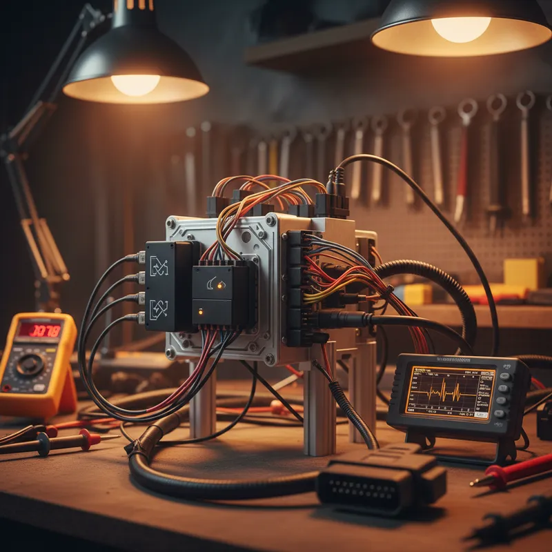
AutoPi CAN-FD Pro: High-Speed CAN-FD Data Logging for ADAS and EV Development
5 Apr · 7 min
Driver Behaviour Scoring for Fleet Safety: Using AutoPi Telematics in India
5 Apr · 7 min

Geofencing and Route Compliance for Indian Fleets: AutoPi Telematics
5 Apr · 6 min

Emulating Processor Power for Thermal Testing: Why Constant Power
7 Oct · 7 min

CRPS and Rack Power Supply Testing: The Six Tests That Matter
7 Oct · 7 min


