

Production boards are getting smaller, ECUs ship fully encapsulated, and test points disappear from layouts. When physical probe access shrinks, boundary scan becomes the primary method for verifying solder joints and interconnections at scale. ProMik’s Boundary Scan Suite brings this capability to production lines with fully automated test generation, no expert knowledge required.
What Is Boundary Scan Testing?
Boundary scan, defined by IEEE 1149.1, is a digital test method that verifies circuit boards and ICs without physical probes. Every boundary-scan-compliant IC contains a test access port (TAP) and boundary scan cells along its I/O pins. Through a standard JTAG interface, a test system can drive signals onto board traces and read them back, detecting shorts, opens, soldering issues, and interconnect faults, all digitally.
Two core tests make up the boundary scan workflow. Infrastructure test verifies the JTAG chain itself: are all boundary-scan-capable devices connected, powered, and responding correctly? Interconnect test goes further, checking the physical connections between devices on the board, confirming that nets are intact and that no unintended shorts exist.
How ProMik’s Boundary Scan Suite Works
ProMik’s approach eliminates the traditional barrier to boundary scan adoption: test development complexity.
The suite generates tests fully automatically from three standard inputs:
- ODB++: the board layout data, describing every net, pad, and component placement
- BSDL: Boundary Scan Description Language files for each IEEE 1149.1 device, describing its TAP and cell structure
- BOM: the bill of materials, identifying which components are populated
From these three inputs, the Boundary Scan Suite produces a complete test program covering infrastructure test and interconnect test. No manual test vector writing. No scripting. The GUI-based test development environment is designed so that production engineers can create and maintain tests without specialized boundary scan expertise.
Key Features
- Blacklisting: exclude specific nets or devices from testing when needed (e.g., unpopulated variants, known exceptions)
- Coverage reporting: see exactly which nets and connections are tested, and which fall outside boundary scan coverage
- Detailed error reporting: when a test fails, the system identifies the specific fault type and location (short, open, or soldering defect)
- No debug interface required: test encapsulated or boxed ECUs where debug connectors are inaccessible
Where Boundary Scan Fits Best
Boundary scan testing is particularly valuable in scenarios where traditional in-circuit test (ICT) cannot reach:
- Miniaturized designs with fine-pitch BGAs and limited test pad access
- Encapsulated ECUs where the board is sealed inside a housing before test
- Boards with limited physical access due to component density or mechanical constraints
For automotive electronics production in India, where ECU complexity is increasing rapidly with ADAS, EV, and domain controller programs, boundary scan provides a scalable quality gate that does not depend on physical probe fixtures.
Integration Options
ProMik offers the Boundary Scan Suite in two forms:
- FlashTask Pro: ProMik’s production-grade flash programming platform, which integrates boundary scan testing alongside programming. Same hardware, same interface, same software, same workflow. A single station handles both programming and board-level test.
- DLL for sequencer integration: for production lines already using test sequencers like LabVIEW or TestStand, ProMik provides a DLL that integrates boundary scan into existing test sequences.
The MSP2300net flash programming system supports this combined workflow, enabling production teams to consolidate programming and test onto one platform.
Why Buy ProMik Boundary Scan Tools from GSAS India
GSAS Micro Systems is the authorized engineering partner in India. Our team in Bengaluru, Hyderabad, and Pune provides pre-sales evaluation support, integration assistance, and after-sales service for ProMik’s full product range, including the Boundary Scan Suite, FlashTask Pro, and all flash programming hardware.
If your production line tests miniaturized boards, encapsulated ECUs, or high-density assemblies, boundary scan belongs in your test strategy. Contact GSAS to discuss your requirements or schedule a demonstration.
Also appears in:
Interested in ProMik tools?
Talk to our application engineers for personalized tool recommendations.
More from ProMik
View all →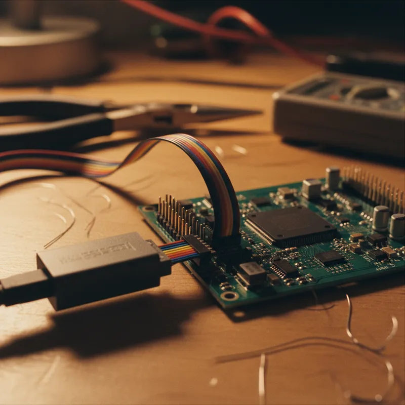
Automotive ECU Programming and Traceability: Meeting IATF 16949 with ProMik
5 Apr · 7 min

Scaling Electronics Manufacturing in India: Programming Infrastructure for Growth
5 Apr · 7 min
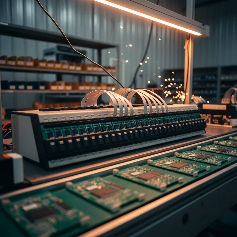
FlashTask Pro: Production Programming Project Management with ProMik
5 Apr · 7 min
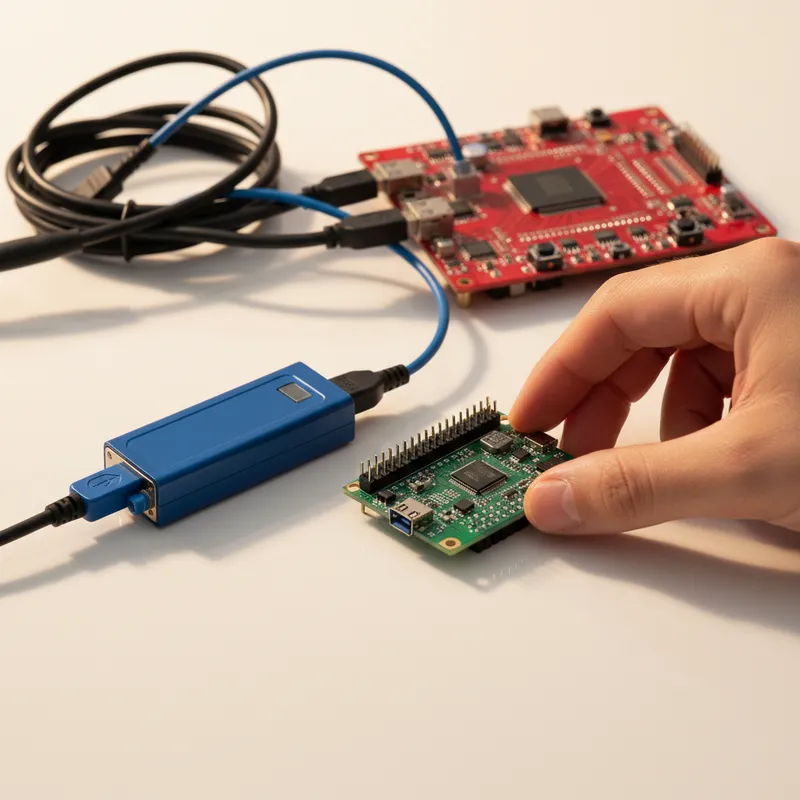
Gang Programmer vs Inline ISP: Choosing the Right Production Programming Approach
5 Apr · 7 min

Emulating Processor Power for Thermal Testing: Why Constant Power
7 Oct · 7 min

CRPS and Rack Power Supply Testing: The Six Tests That Matter
7 Oct · 7 min


