
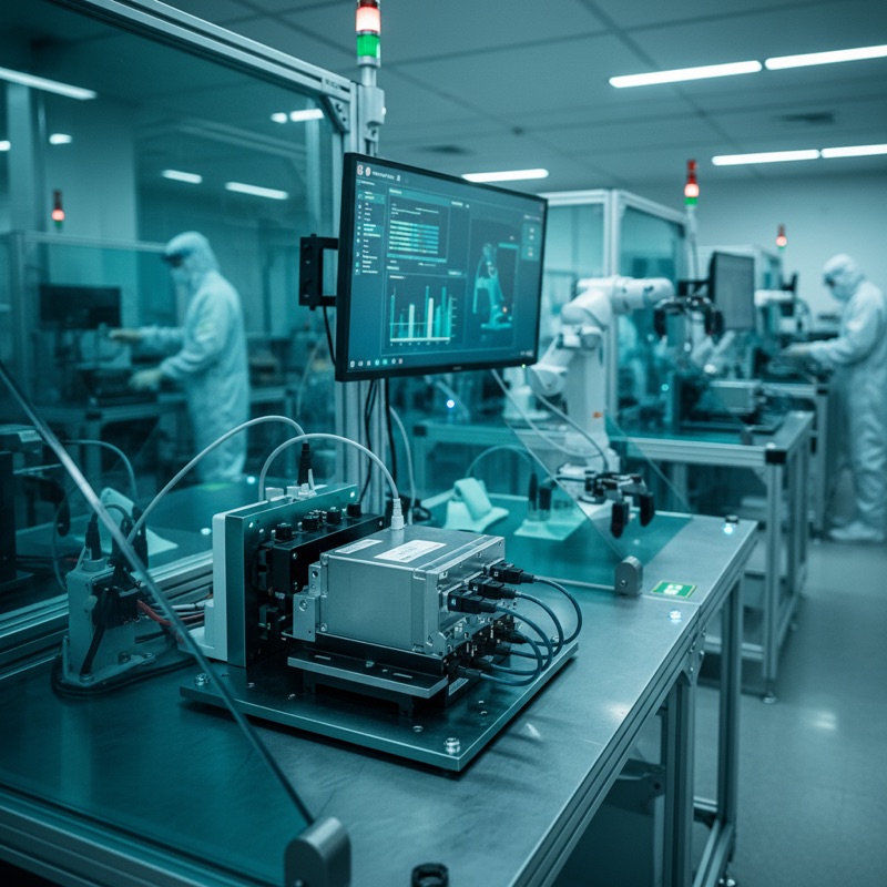
End-of-line testing is where quality is proven. It is the last production step before a product ships, the final gate where defects must be caught or they reach the customer. For automotive ECUs, this stage carries particular weight: a unit that passes end-of-line testing is deemed production-ready, and any latent defect that escapes becomes a field failure with safety and warranty implications.
The challenge intensifies when the ECU is encapsulated. Once a control unit is sealed in its housing, potted, conformal-coated, or simply mechanically closed, the debug interfaces (JTAG, SWD) that were accessible during board-level programming and test are no longer available. Traditional test approaches that rely on bed-of-nails fixtures contacting test pads on the bare PCB cannot reach a boxed unit.
ProMik addresses this with an integrated end-of-line testing approach that combines flash bootloader technology with comprehensive functional test capabilities, validating even sealed ECUs through their production connectors.
High-Speed Programming via Production Connectors
ProMik’s end-of-line solution uses the connectors that remain accessible on the encapsulated ECU: USB and Automotive Ethernet interfaces. High-speed programming through these production connectors eliminates the need for debug access, enabling software upload and boot operations on fully assembled and sealed units.
This is not a compromise, it is by design. Modern automotive ECUs are architected with bootloader protocols that support secure firmware updates through standard vehicle interfaces. ProMik’s toolchain exploits these bootloader capabilities to deliver production-grade programming speed through the same connectors the ECU will use in the vehicle.
Customization Tasks: Beyond Simple Flashing
End-of-line programming is rarely just a binary upload. ProMik’s integrated approach handles the full range of customization tasks that occur at the final production step:
- Software upload and boot: Complete firmware deployment and initial boot verification
- Serial number writing: Unique identification programming for traceability
- Cybersecurity key injection: Secure provisioning of cryptographic keys and certificates
These operations must execute reliably at production speed, with full traceability. ProMik’s FlashTask Pro software manages the sequencing, logging, and verification of each step.
Deep-Level Functional Testing
What distinguishes ProMik’s end-of-line approach from a simple flash-and-ship workflow is the depth of functional testing that follows programming. The same toolchain that handles firmware upload also executes:
- Interface and communication tests: Verifying that all communication buses (CAN, LIN, Ethernet, USB) respond correctly after firmware deployment
- Frequency tests and current tests: Measuring electrical parameters to confirm hardware integrity
- Diagnostic tests: UDS (Unified Diagnostic Services) or DoIP (Diagnostics over IP) protocol exchanges that exercise the ECU’s diagnostic stack
- Restbus simulations: Simulating the vehicle network environment so the ECU operates as it would in the complete vehicle, enabling functional verification without a full vehicle harness
This combination enables deep-level functional testing even for encapsulated or boxed ECUs, no debug interface required. The production connector provides sufficient access for both programming and comprehensive functional verification.
One Software for All Steps
A critical architectural decision in ProMik’s approach is the use of one software platform for all steps, from flash to full functional test. Rather than requiring separate tools for programming, customization, and functional verification, each with its own configuration, logging, and operator interface, ProMik consolidates the entire end-of-line sequence into a single software environment.
This consolidation reduces operator training requirements, eliminates hand-off errors between separate tools, and ensures that traceability data from every step, programming, customization, functional test, is captured in a unified log. For automotive customers subject to IATF 16949 and OEM-specific traceability requirements, this single-source logging simplifies audit preparation and defect root-cause analysis.
Traceability and Test Coverage at the Last Production Step
End-of-line testing is the final opportunity to establish a complete quality record for each unit. ProMik’s solution ensures traceability and test coverage at this last production step, capturing programming verification data, functional test results, and cybersecurity provisioning records in a structured format suitable for MES (Manufacturing Execution System) integration.
For ECUs destined for safety-critical applications, braking, steering, powertrain, this traceability record is not optional. It is a contractual and regulatory requirement that the end-of-line system must satisfy without exception.
Why This Matters for Indian Automotive Manufacturing
India’s automotive electronics manufacturing is maturing rapidly. As Indian OEMs and Tier-1 suppliers move from importing programmed ECUs to in-house production, the need for capable end-of-line testing infrastructure grows proportionally. Encapsulated ECU testing is no longer a niche requirement, it is standard practice for any production line handling sealed control units.
GSAS Micro Systems is the authorized ProMik engineering partner in India, supporting automotive production teams with end-of-line testing solutions across Bengaluru, Hyderabad, Chennai, Pune, Mumbai, Delhi NCR, and Visakhapatnam. From initial process design through production validation and ongoing support, our engineers work alongside manufacturing teams to deploy ProMik’s integrated flash-and-test solutions.
Discuss your end-of-line testing requirements | Explore ProMik solutions
Also appears in:
Interested in ProMik tools?
Talk to our application engineers for personalized tool recommendations.
More from ProMik
View all →
Automotive ECU Programming and Traceability: Meeting IATF 16949 with ProMik
5 Apr · 7 min

Scaling Electronics Manufacturing in India: Programming Infrastructure for Growth
5 Apr · 7 min
FlashTask Pro: Production Programming Project Management with ProMik
5 Apr · 7 min
Gang Programmer vs Inline ISP: Choosing the Right Production Programming Approach
5 Apr · 7 min

Emulating Processor Power for Thermal Testing: Why Constant Power
7 Oct · 7 min

CRPS and Rack Power Supply Testing: The Six Tests That Matter
7 Oct · 7 min


