
pyPicoSDK: Getting started
Introduction
Pico Technology provides a wide range of PC-based oscilloscopes that can be controlled and automated using software. For Python developers, pyPicoSDK offers a convenient way to interface with PicoScope devices, enabling tasks such as data capture, automation, and analysis directly within Python scripts.
This approach is especially useful for engineers and researchers who want to integrate oscilloscope measurements into automated test setups, signal processing workflows, or data analysis pipelines.
Step 1: Install PicoSDK
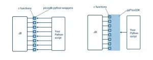
Before using pyPicoSDK, you need to have the official PicoSDK drivers installed. These drivers act as the communication layer between your computer and the PicoScope hardware.
-
The SDK can be downloaded from Pico Technology’s official website.
-
Choose the installer that matches your operating system (Windows, Linux, or macOS).
Step 2: Install pyPicoSDK (Python Wrapper)
Once the drivers are ready, you can install the Python wrapper using pip:
pip install pypicosdkThis package provides Python bindings for the C-based PicoSDK libraries.
Step 3: Import pyPicoSDK in Your Python Project
After installation, you can start writing Python scripts. To load the library, simply import it:
import pypicosdk as psdkStep 4: Quick Test Script
Here’s a minimal script to test your setup:
scope = psdk.ps6000a()
scope.open_unit()
print(scope.get_unit_serial())
scope.close_unit()
If everything is working correctly, this script will open the oscilloscope, print the device’s serial number, and then close the connection.
Step 5: Explore Example Scripts
pyPicoSDK includes a set of example scripts on GitHub that demonstrate how to configure the scope, capture signals, and process the data. Running these examples is the best way to get familiar with the library’s capabilities.
Supported Devices
Currently, pyPicoSDK supports:
-
PicoScope 6000E Series (via the
ps6000adriver) -
PicoScope 3000E Series (via the
psospadriver)
More device families are expected to be added in the future as development progresses.
Why Use pyPicoSDK? (Theory)
Traditionally, oscilloscopes are controlled through vendor-specific GUI applications. While convenient, this limits flexibility in automated testing and integration with custom workflows. By exposing the hardware API through Python:
-
Engineers can integrate oscilloscopes into larger automated test systems.
-
Researchers can directly analyze captured data using libraries like NumPy, SciPy, or Matplotlib.
-
Developers can build custom measurement solutions that go beyond the scope of standard oscilloscope software.
In short, pyPicoSDK bridges the gap between PicoScope hardware and Python’s powerful ecosystem for scientific computing.
Also appears in:
Interested in Pico Technology tools?
Talk to our application engineers for personalized tool recommendations.
More from Pico Technology
View all →
How to Buy an Oscilloscope in India (2026): USB vs Benchtop, Bit Depth, Bandwidth: A Buying Guide
5 Jun · 11 min
PicoScope 5000D vs 5000E: Native 16-Bit or FlexRes? A Buyer's Guide for Indian Labs
4 Jun · 11 min
PicoScope 5000E in India: The World's First 4-Channel 16-Bit USB Oscilloscope, Explained
4 Jun · 11 min
PicoScope 7 Goes Native Arm64: Apple Silicon, Snapdragon Windows and Arm Linux Test Benches in India
4 Jun · 11 min

Emulating Processor Power for Thermal Testing: Why Constant Power
7 Oct · 7 min

CRPS and Rack Power Supply Testing: The Six Tests That Matter
7 Oct · 7 min


