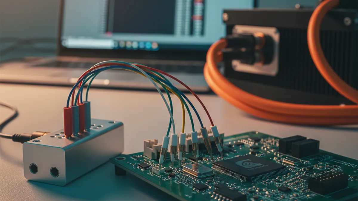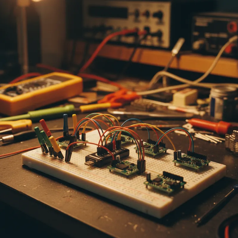
There is a moment in every embedded board bring-up where a developer in Bengaluru, Pune, or Chennai has the board on the bench, the analyzer connected, and a screen full of waveforms that are almost but not quite the protocol they expected. This post is for that moment.
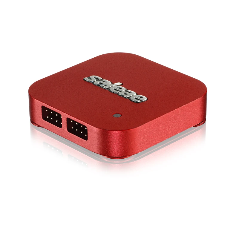
We’re going to walk through the practical decode workflow for the three protocols every embedded engineer in India will touch this year, I²C, SPI, and UART, using Saleae Logic 2 and any of the current Saleae Logic family devices. The same patterns apply on Logic 8, Logic Pro 8, and Logic Pro 16. The Logic MSO line adds analog precision but the protocol-decode workflow is identical.
This is not a tour of the GUI. Saleae’s own Support docs cover that better than we can. This is the workflow that gets a stuck bring-up unstuck.
Before you capture anything
Two things to do before you connect a probe.
One, pull the datasheet for the target part open, find the protocol section, and write down three things: the bus speed in nominal MHz, the idle state of each line, and what the first transaction after reset is supposed to look like. For an I²C sensor that might be 100 kHz, SCL and SDA idle high, first transaction is a probe write to register 0x00. For an SPI flash, up to 50 MHz, CS idle high, first transaction after power-up is a JEDEC ID read (0x9F). Knowing what you expect is what lets you spot what’s actually happening.
Two, set the logic threshold correctly. If you’re on a Logic Pro 8 or Logic Pro 16, the threshold is selectable: +0.6 V, +0.9 V, or +1.65 V. The default is +1.65 V, which is wrong for any modern SoC running at 1.8 V or 1.2 V logic levels. We see at least one team per quarter capture six hours of garbage because the threshold defaulted to +1.65 V on a 1.8 V signal. Set it to +0.9 V for 1.8 V signaling and +0.6 V for 1.2 V or lower. The Logic 8 doesn’t have a selectable threshold, which is why we don’t recommend it for current-generation Arm SoCs.
I²C: the protocol that fails clearly when it fails
I²C is forgiving by design and unforgiving when something is wrong. The three failure modes you’ll see, in roughly the order you’ll see them:
Failure 1: no acknowledgement
You see SCL clocking, SDA going down for an address byte, and then no ACK. The target isn’t responding. Always check, in this order:
- The pull-ups exist and are connected. I²C is open-drain, no pull-ups, no protocol. This is the #1 cause of “the bus doesn’t work” in lab environments. Logic 2 shows you the rise time of the lines clearly; a slow, exponential rise means the pull-ups are missing or too weak.
- The address is right. Saleae’s I²C decoder shows the 7-bit address with the R/W bit visualised separately. Confirm it matches the datasheet, not the “this is what I wrote in my driver” address, the actual byte on the bus. People shift addresses by one bit constantly. The decoder removes that ambiguity.
- The target has power and isn’t being held in reset. Sounds obvious; we’ve watched experienced engineers spend half a day on this one.
Failure 2: clock stretching that nobody expects
The target pulls SCL low after the ACK and holds it for tens of microseconds before releasing. The decoder will show this as a gap, the SCL line going flat at zero. If your driver doesn’t handle clock stretching (and many lightweight bare-metal drivers don’t), the next bit will be sent before the target is ready. Either fix the driver to wait for SCL release, or slow the bus down.
Failure 3: the bus locks up
You see one half-completed transaction and then both lines stuck. Usually the target was reset mid-transaction and is waiting for a clock pulse it never got. Generate nine clock pulses with SDA released to unstick the bus, or power-cycle. Logic 2 will show the locked state clearly, SDA stuck low, SCL idle high.
The decode setup
Add the I²C analyzer in Logic 2 (+ button in the right panel, search “I2C”), select your SDA and SCL channels, leave Address Display as 7-bit. The decoder doesn’t need any other configuration, clock stretching, multi-master, repeated starts all decode automatically. For Indian sensor-hub teams running multiple devices on the same bus, the Protocol Search feature filters captures to specific addresses in one click, much faster than scrolling.
SPI: the protocol that needs you to be right about four things at once
SPI is faster, simpler in spec, and harder in practice because there’s no acknowledgement and no clock stretching. If the timing is wrong, you just get garbage with no error frame to grab onto.
The four things you have to be right about
- Clock polarity (CPOL): 0 means SCK idles low, 1 means SCK idles high
- Clock phase (CPHA): 0 means data sampled on the leading edge, 1 means trailing
- Chip select polarity: almost always active-low (CS goes low to select), but check the datasheet
- Bit order: MSB-first is the default; some parts (notably some older sensor families) are LSB-first
Saleae’s SPI decoder needs all four of these set correctly. The most common bring-up failure is CPOL/CPHA mismatch, the decoded bytes will be plausible-looking nonsense, often shifted by half a bit, and the developer spends an hour wondering why the SPI flash JEDEC ID is 0xC8 0xE0 0x18 instead of 0xC2 0x20 0x18. Half-bit shift is the tell. Swap CPHA, recapture, the world makes sense.
The bring-up sequence
For a new SPI flash on a new board, the canonical first transaction is the JEDEC ID read, write 0x9F, then read 3 bytes. Three known-good bytes back means clock, CS, MOSI, MISO, and CPOL/CPHA are all right. From there, almost everything works.
For a new SPI sensor (accelerometer, IMU, magnetometer), the first transaction is usually a WHO_AM_I register read. The datasheet will tell you the read command format and the expected response byte. Same idea, known input, known expected output, and the analyzer tells you which one is wrong if they don’t match.
Logic Pro 8 vs Pro 16 for SPI
For most SPI work, 4 channels (SCK + CS + MOSI + MISO) is enough, Logic 8 or Logic Pro 8 covers it. When the SPI bus has multiple chip-selects (an SPI flash + an SPI sensor + an SPI display all sharing the same SCK/MOSI/MISO with different CS lines), the channel count climbs quickly. Two devices means 6 channels; three means 7. Past that you’re on a Logic Pro 16.
UART: the protocol that lies to you about success
UART will happily clock garbage out one end and garbage in at the other and never tell you anything is wrong. There is no framing-error signal you can trust without parity. The way you debug UART is by catching mismatched baud rates fast and decoding to ASCII immediately.
The bring-up sequence
Connect TX, RX, and GND (always GND, UART is referenced to ground, not USB ground, not analyzer ground, the actual signal ground of the target board). Set the analyzer to the baud rate your driver claims it’s using, typically 115,200 or 9600 for most embedded console UARTs in India.
Capture for 5 seconds. Open the decoded data table. If you see clean ASCII text (or your expected binary protocol bytes), you’re done. If you see consistent garbage, \x80 \xC0 \x80 \xC0 repeating, or random high-bit bytes, the baud rate is wrong. Try 115,200 → 57,600 → 38,400 → 9600. One of them will produce clean output. That’s your real baud rate.
The bring-up trick that saves hours
Right-click the UART decoder in Logic 2 → Settings → check “Show in protocol search”. Then in the search panel, search for a known string you expect to see at boot, "Boot" or "Reset" or your bootloader’s prompt. If it’s there, Logic 2 will jump to it. If it’s not, your TX/RX are crossed or the boot isn’t actually printing.
What changes when you move to a Logic MSO
The MSO line (Saleae Logic MSO 4×200 and siblings) gives you 100 MHz or 200 MHz analog bandwidth alongside the same 8-channel digital capture and the same Logic 2 protocol decoders. For the three protocols above, the digital workflow is identical, but you can simultaneously watch the supply rails, the chip-select edges, or any analog measurement on the same timebase. For boards where I²C bus failures correlate with rail glitches, the MSO line is a step up. For pure digital protocol debug, the Logic family stays the right tool.
What GSAS does
A GSAS field application engineer will sit at your bench in Bengaluru, Hyderabad, Chennai, Pune, Mumbai, or Delhi NCR and run through these exact workflows on your actual board with your actual signals. We’ve debugged hundreds of I²C, SPI, and UART bring-ups across automotive, semiconductor design, medical-device, and industrial-automation customers in India. The half-day bench visit is included with the Saleae purchase, we don’t bill for pre-sales engineering.
Request a Quote for India pricing on the Saleae product line, or Contact us for a bench visit.
Also appears in:
Interested in Saleae tools?
Talk to our application engineers for personalized tool recommendations.
More from Saleae
View all →
Saleae Logic MSO: Standard or Pro? The India Buying Decision
17 Jul · 6 min
Best Logic Analyzer in India (2026): A Vendor-Neutral Buying Guide for Embedded Teams
5 Jun · 10 min
AI Data Centers in India: Test, Measurement & Memory Boom
4 Jun · 14 min
Logic Analyzer vs Oscilloscope vs MSO: When You Actually Need Analog Channels (Saleae Logic MSO)
4 Jun · 10 min

Emulating Processor Power for Thermal Testing: Why Constant Power
7 Oct · 7 min

CRPS and Rack Power Supply Testing: The Six Tests That Matter
7 Oct · 7 min