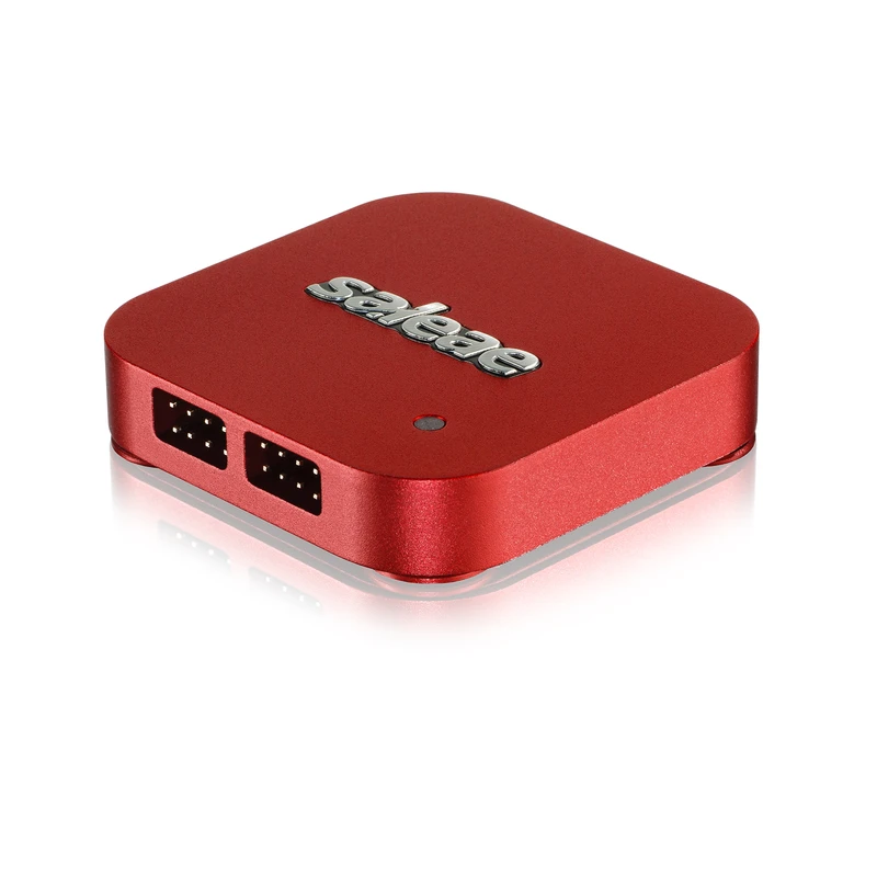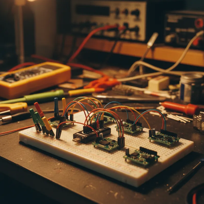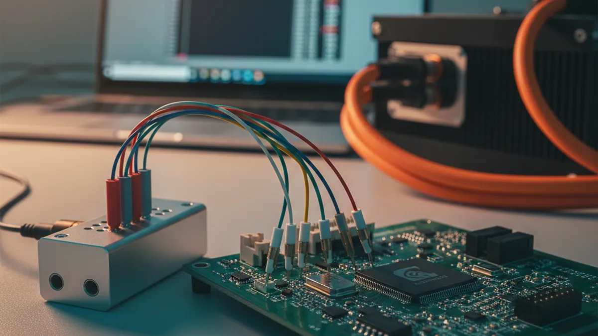
Walk onto almost any ECU bench in Bengaluru, Pune or Chennai today and the three protocols on the probe will be the same: CAN, CAN-FD, and LIN. Body controllers, instrument clusters, EV powertrain inverters, two-wheeler ECUs, BMS slave boards, all of them talk on these buses, and all of them eventually misbehave in a way that needs a logic analyzer to explain.
Our I²C, SPI and UART bring-up workflow deliberately left the automotive buses out. This post is the missing chapter: how to capture and decode CAN, CAN-FD and LIN with Saleae Logic 2 on a real automotive board, and, more importantly, the one thing about where to probe that the marketplaces and clone sellers never tell you.
Everything below is verifiable against Saleae’s own protocol-analyzer support docs. No invented specs.
Read this before you clip onto a CAN bus
Here is the caveat that saves boards, probes, and afternoons. It is the single most important sentence in this entire post.
You do not probe the differential CAN bus. You probe the single-ended side of the CAN transceiver.
Saleae says this plainly: “none of the Saleae products have differential inputs. They are single-ended only.” For CAN specifically, their guidance is: “The recommended way to record CAN data is to probe the single-ended signal between the CAN transceiver IC and the application processor.”
What that means on your actual board:
- A CAN node has a transceiver IC (TJA1042, TCAN1042, MCP2542, and friends) that sits between the differential bus (CAN_H / CAN_L) and the microcontroller’s CAN controller.
- On the bus side of the transceiver you have CAN_H and CAN_L, a differential pair swinging around 2.5 V. Do not clip a Saleae channel here.
- On the controller side of the transceiver you have two single-ended, logic-level lines: CAN TX (MCU → transceiver) and CAN RX (transceiver → MCU). This is where the Saleae probe goes.
The RX line carries everything on the bus that the node can see, your own transmissions and every other node’s frames, already converted to clean single-ended logic. One channel on CAN RX, one ground, and you can decode the whole bus. If you want to separate what this node sent from what it received, capture CAN TX on a second channel.
If you genuinely cannot reach the transceiver pins, a sealed module, a connector-only test point, you have two fallbacks, both documented by Saleae. You can record one side of the differential pair (CAN_L) referenced to ground, or you can put a differential-to-single-ended receiver between the bus and the analyzer. Neither is as clean as probing CAN RX, but both beat clipping both differential lines and hoping.
The same rule applies to LIN, with one difference: LIN is already a single-wire bus, but it swings to the battery rail (12 V on a car, often 48 V on newer architectures). You probe the LIN signal on the controller side of the LIN transceiver, where it has been level-shifted down to MCU logic, not the raw 12 V / 48 V bus line. Saleae’s inputs have an operating range of −10 V to +10 V (±25 V absolute max on the Logic Pro 8 / Pro 16); a raw automotive LIN line is outside that range. Probe past the transceiver.
This is the part the grey-market listings and “Saleae compatible” clone pages never explain, and the part that, in our experience, separates a clean ECU capture from a damaged input. Get the probe point right first.
Setting the logic threshold for automotive logic levels
Before any decode, set the threshold to match the controller-side logic, not the car.
The transceiver outputs CAN RX/TX and LIN RX/TX at the MCU’s logic level, which on a modern automotive Arm Cortex-M or Cortex-R part is usually 3.3 V, sometimes 1.8 V on the newer high-integration SoCs. On a Logic Pro 8 or Logic Pro 16, the threshold is selectable at +0.6 V, +0.9 V, or +1.65 V. Use +1.65 V for 3.3 V signalling and +0.9 V for 1.8 V signalling. The entry Logic 8 has a fixed threshold, which is fine for 3.3 V controller-side lines but is why we steer current-generation 1.8 V ECU work toward the Pro tier.
Getting the threshold wrong is the second most common cause of “the decoder shows nothing” after probing the wrong side of the transceiver.
CAN: what Saleae decodes, and how to set it up
CAN is the workhorse. Once your probe is on CAN RX and your threshold is right, the decode itself is straightforward.
Adding the CAN analyzer
In Logic 2, open the Analyzers panel, add the CAN analyzer, and point it at your CAN RX channel. The one setting that matters is bit rate. Saleae’s guide is explicit: “If you already know the bit rate your CAN bus is using, enter it here.” For most Indian vehicle and EV applications that’s 500 kbit/s on the powertrain/chassis bus and 125 kbit/s or 250 kbit/s on body/comfort buses, but confirm against the network specification, never guess.
If you don’t know the bit rate, Saleae documents “several easy ways to measure this” from the captured waveform, the shortest bit time on the bus gives you the nominal rate.
What you get back
The Saleae CAN analyzer “supports standard and extended CAN identifiers”, both 11-bit (CAN 2.0A) and 29-bit (CAN 2.0B) IDs. It decodes the identifier, the control field, the data field, the CRC value, and the ACK / NAK response. That is exactly the set of fields you need to answer the questions that actually come up at the bench:
- Is my node even on the bus? Look at the ACK slot. If your node’s frame goes out and nothing acknowledges it, you’re alone on the bus (no other node, wrong bit rate, or termination missing).
- Is the arbitration ID what my driver thinks it is? The decoder shows the ID on the wire, not the ID in your code. Endianness and ID-shift bugs surface instantly.
- Is the DLC and payload right? The data field is decoded byte-for-byte. Match it against your DBC / message definition.
- Is the bus healthy? A storm of error frames or a node that’s gone bus-off shows up as malformed frames the decoder flags rather than clean traffic.
For a board with several CAN nodes, use Protocol Search in Logic 2 to filter the capture down to a single arbitration ID in one click, far faster than scrolling a busy 500 kbit/s capture by hand.
CAN-FD: read this carefully
Here is where honesty matters more than a marketing line, and where this post earns the click over a marketplace listing.
CAN-FD is not a built-in Saleae analyzer. Saleae’s bundled protocol stack covers classical CAN (2.0A / 2.0B). CAN-FD, with its flexible data-rate phase and up to 64-byte payloads, is tracked as an open feature request on Saleae’s own ideas portal, and decode is handled through community-contributed analyzers and the Logic 2 Marketplace rather than the built-in stack.
So how do you actually decode CAN-FD on a Saleae today? Two supported paths, both documented:
- Logic 2 Marketplace / community analyzer. Logic 2 has an in-app marketplace of community-contributed analyzers. CAN-FD decoders live here. Install one, point it at your CAN RX channel, set the nominal and data bit rates, and you get FD frames decoded, including the longer payloads and the BRS (bit-rate switch) behaviour.
- A High-Level Analyzer (HLA) in Python. Saleae’s HLA framework lets you build an application-layer decoder on top of a lower-level capture. For teams that need CAN-FD frames mapped to their own UDS / autosar-style application semantics, an HLA is the clean, version-controllable answer.
The raw capture is never the problem, a Saleae streams the CAN RX line at far above CAN-FD’s data-phase rate. What you’re choosing is which decoder turns those edges into frames. We say this plainly because a clone-seller’s listing will happily imply “CAN-FD supported” with no asterisk. The correct, verifiable statement is: CAN-FD on Saleae is a community/Marketplace or HLA decode, not a built-in analyzer. Plan accordingly.
When the Saleae is the wrong tool for CAN-FD: and what is
A Saleae logic analyzer is a passive, read-only observer. It watches a bus; it does not talk on one. If your job is to generate CAN-FD traffic, inject frames, replay a sequence, stimulate an ECU under test, act as a bench node, you want an active CAN-FD adapter. That’s a different instrument class. For that, see our CAN-FD bus testing workflow with the Binho Pulsar, which covers active frame generation for ECU validation. The two are complementary: Binho talks, Saleae watches. Many Indian Tier-1 benches run both.
LIN: the slow bus that hides slow bugs
LIN is the cheap, single-master, low-speed bus behind seat controls, mirror motors, rain sensors, ambient lighting, and the dozens of small body-comfort nodes in a modern vehicle. It runs at modest bit rates (commonly 9.6, 19.2, or up to 20 kbit/s), which is exactly why people under-debug it, until a checksum mismatch or a wrong PID stalls a whole sub-network.
Adding the LIN analyzer
Add the LIN analyzer in Logic 2 and point it at the controller-side LIN RX line (again, past the transceiver, not the 12 V bus). LIN is an asynchronous protocol, so, like CAN and async serial, the bit rate must be set accurately for the decoder to produce valid frames. Enter the bit rate from your LIN network description (LDF) file.
What the LIN decoder shows
Saleae’s LIN analyzer decodes the full frame structure: the break, the sync field, the protected identifier (PID), the data bytes, and the checksum. That maps directly to how LIN fails in practice:
- No sync / no break detected → your master isn’t actually driving the header, or you’re on the wrong line.
- PID parity wrong → the 6-bit ID is right but the two parity bits aren’t; usually a master-side frame-table bug.
- Checksum mismatch → classic LIN gotcha. LIN has classic (data-only) and enhanced (data + PID) checksum modes. A master and slave that disagree on which mode to use produce frames where every other field looks perfect and only the checksum is “wrong.” The decoder showing a clean frame with a bad checksum is your tell, go check the checksum model on both ends.
One honest decoder note from Saleae worth knowing: the LIN analyzer “may be unable to determine if a byte is a data byte or checksum” in the edge case where a data byte happens to be numerically valid as the checksum for a shorter frame. In normal traffic with a known frame length from your LDF this never bites you, but it’s why you set the expected data length rather than letting the decoder guess.
A complete automotive bench setup, in order
Putting it together, here’s the sequence we run on a customer’s ECU bench:
- Identify the transceiver for each bus you care about (CAN, CAN-FD, LIN). Find its controller-side RX/TX pins.
- Clip the Saleae on the controller side: CAN RX (and TX if you want direction), LIN RX. Add a solid ground to the board’s signal ground.
- Set the threshold to the MCU logic level (+1.65 V for 3.3 V, +0.9 V for 1.8 V on a Pro 8 / Pro 16).
- Add the analyzers: built-in CAN, built-in LIN, Marketplace/HLA for CAN-FD. Set each bit rate from the network spec.
- Capture a known event: power-up, a wake message, a specific CAN command, so you have a known-input / known-output reference.
- Use Protocol Search to jump to the arbitration ID or LIN PID in question instead of scrolling.
- For regression, drive the whole thing from the Logic 2 Python Automation API so your ECU’s bus behaviour is captured and diffed against a known-good
.salbaseline on every nightly build.
That last step is what turns a bench tool into a CI asset, the same workflow Indian EV and Tier-1 teams use to catch a bus regression before it reaches the vehicle.
Which Saleae for automotive ECU work
For automotive bus debug specifically:
- Logic Pro 8: 8 channels is enough for one or two buses plus their TX/RX split and a couple of trigger/reset lines. Selectable thresholds handle 3.3 V and 1.8 V controller-side logic. The most common pick for a single-ECU bench.
- Logic Pro 16: when one capture must cover several buses at once: CAN + CAN-FD + LIN + the SPI to the BMS front-end + chip-selects, all on one timebase. The gateway and domain-controller teams live here.
- Logic MSO line: adds analog bandwidth alongside the digital channels, so you can watch a supply rail or a transceiver’s bus-side voltage on the same capture as the decoded frames. Useful when a CAN fault correlates with a power event. See why MSO matters.
The digital decode workflow above is identical across all of them, the choice is channel count and whether you need analog on the same timebase.
Frequently asked questions
Can a Saleae logic analyzer decode the differential CAN_H / CAN_L bus directly?
No. Saleae devices are single-ended only, “none of the Saleae products have differential inputs.” Probe the single-ended CAN RX/TX lines between the CAN transceiver IC and the microcontroller, not the differential bus. If you can only reach the bus, record one side of the pair referenced to ground, or use a differential-to-single-ended receiver first.
Does Saleae support CAN-FD decode out of the box?
Not as a built-in analyzer. Classical CAN (2.0A / 2.0B, standard and extended IDs) is built in. CAN-FD decode is handled via a Logic 2 Marketplace / community analyzer or a custom Python High-Level Analyzer, and full built-in CAN-FD support is an open feature request on Saleae’s ideas portal. The hardware captures the line fine; you choose the decoder.
What bit rate should I set for the CAN analyzer?
Set it to the bus’s actual nominal bit rate from the network specification, commonly 500 kbit/s for Indian powertrain/chassis buses and 125–250 kbit/s for body/comfort buses. If unknown, Saleae documents measuring it from the captured waveform’s shortest bit time. The analyzer needs an accurate bit rate to produce valid frames.
Where do I probe a 12 V automotive LIN bus safely?
On the controller side of the LIN transceiver, where the signal has been level-shifted to MCU logic, never the raw 12 V (or 48 V) bus line. Saleae inputs operate over −10 V to +10 V (±25 V absolute max on Logic Pro 8 / Pro 16); the raw LIN line exceeds that. Probe past the transceiver.
Can I use Saleae to inject or generate CAN/LIN traffic for an ECU under test?
No, a Saleae is a passive, read-only protocol analyzer. To actively generate CAN-FD frames and stimulate an ECU, use an active adapter such as the Binho Pulsar for CAN-FD ECU validation. Saleae watches the bus; Binho talks on it. Indian Tier-1 benches commonly run both.
Does the automotive decode workflow run on macOS and Linux?
Yes. Logic 2 ships a single binary for Windows 10/11, macOS (Intel and Apple Silicon), and Linux x86, and the CAN / LIN analyzers and Python Automation API behave identically across all three.
Talk to GSAS about your automotive bench
GSAS is an authorized India engineering partner. A GSAS field application engineer will sit at your ECU bench in Bengaluru, Hyderabad, Chennai, Pune, Mumbai, or Delhi NCR, find the right transceiver-side probe points on your actual board, and capture your live CAN, CAN-FD and LIN traffic in Logic 2 before you raise a purchase order, you see the decode running on your hardware first. We support automotive, EV powertrain, and two-wheeler ECU teams across the automotive and two-wheelers & EV verticals, and the pre-sales bench visit is included.
Request a Quote for India pricing, GST invoicing, and current lead time on the Saleae Logic line, or Contact us to book a bench visit.
Also appears in:
Interested in Saleae tools?
Talk to our application engineers for personalized tool recommendations.
More from Saleae
View all →
Saleae Logic MSO: Standard or Pro? The India Buying Decision
17 Jul · 6 min
Best Logic Analyzer in India (2026): A Vendor-Neutral Buying Guide for Embedded Teams
5 Jun · 10 min
AI Data Centers in India: Test, Measurement & Memory Boom
4 Jun · 14 min
Logic Analyzer vs Oscilloscope vs MSO: When You Actually Need Analog Channels (Saleae Logic MSO)
4 Jun · 10 min

Emulating Processor Power for Thermal Testing: Why Constant Power
7 Oct · 7 min

CRPS and Rack Power Supply Testing: The Six Tests That Matter
7 Oct · 7 min