
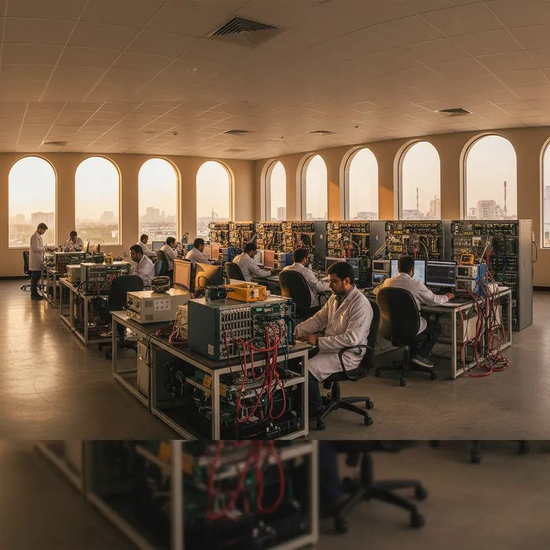
Binho Pulsar for Automotive ECU Peripheral Validation in India
An automotive ECU is not one bus. It is a vehicle network interface bolted onto a board that is mostly conventional embedded hardware: an I2C sensor or two, an SPI NOR flash holding calibration or update images, a UART debug console, sometimes an RS-485 link for diagnostics or a legacy subsystem, and a fistful of GPIO for resets and enables. Validation teams in Pune, Chennai, Bengaluru, and Hyderabad spend a surprising share of their time on that second category, and it is the category the Binho Pulsar addresses well today.
This post is deliberately explicit about what the Pulsar does now versus what Binho has announced but not yet shipped, because getting that boundary wrong is expensive when a validation plan is already written.
Start With the Honest Part: CAN-FD Is Not Shipping Yet
Binho’s Pulsar product page lists CAN-FD under features marked coming soon. Binho’s own published figure for it is up to 5 Mbps, optimized for use in 12 V systems. It is not a capability you can exercise on a Pulsar today, and GSAS does not position the Pulsar as a CAN-FD tool.
The same coming-soon label applies to SPI Peripheral, I2C Peripheral, I2C 10-bit addressing, 1-Wire, and GPIO PWM. Everything below concerns only what Binho lists as available now.
If your ECU programme genuinely needs CAN or CAN-FD bus access this quarter, say so early. GSAS application engineers in Pune and Chennai would rather help you scope the right instrument for the vehicle-network layer than sell you a tool that does not yet reach it. Talk to us about timing before the test plan locks.
What the Pulsar Validates on an ECU Today
Binho specifies the shipping Pulsar interfaces as follows:
| Interface | Binho’s published specification |
|---|---|
| SPI Controller | 50 MHz, up to 4x chip-select signals, all 4 SPI modes, MSB/LSB configurable |
| I2C Controller | 1 MHz, 7-bit addressing, clock stretching, configurable pull-ups |
| UART | 115200 baud, hardware flow control |
| RS-485 | Half-duplex, -7 V to +12 V common-mode input |
| GPIO | 6x digital I/O pins, configurable as interrupts |
| Host link | USB 2.0 High Speed, 480 Mbps, USB Type-C |
| Downstream power | Programmable 1.2 V to 3.3 V |
All the digital interfaces are specified at 1.2 V to 3.3 V, which matters on a modern ECU where the peripheral rails have drifted well below 3.3 V.
SPI Flash and Calibration Images
The 50 MHz SPI controller is the headline number, and on an ECU it is genuinely useful rather than merely impressive. Calibration blobs, bootloader images, and update payloads live on external SPI NOR flash, and a validation engineer needs to read them back, compare them against the expected image, and prove that the ECU’s own write path produced what it claimed. Four chip selects mean a board with a flash device plus an SPI-attached ADC or a secure element can be exercised without rewiring between devices.
I2C Sensor and PMIC Registers
A 1 MHz I2C controller with configurable pull-ups covers standard mode, fast mode, and fast mode plus devices. On an ECU that means the pressure sensors, temperature sensors, IMUs and PMICs whose register state you need to inspect when the application layer is reporting something implausible. Configurable pull-ups matter more than they sound: a bench harness rarely reproduces the board’s own bus loading, and being able to set the pull-up rather than solder one is the difference between a five-minute check and an afternoon.
UART Debug Console
115200 baud with hardware flow control is unglamorous and is what most ECU debug consoles actually run at. The value is having it on the same instrument as the SPI and I2C access, so a single capture session can correlate a console message with the register state that produced it.
RS-485 for Diagnostics and Legacy Subsystems
RS-485 is the Pulsar interface that is easy to overlook and often the most useful in Indian automotive and off-highway work. Binho specifies it as half-duplex with a -7 V to +12 V common-mode input range. That common-mode figure is the number that decides whether a link holds up across a real ground offset between two boxes in a vehicle or a test cell, rather than across a bench jumper. Where a subsystem speaks Modbus RTU or a proprietary RS-485 protocol, the Pulsar taps it directly. Our companion post on RS-485 and Modbus testing with the Binho Pulsar goes deeper on that workflow.
Where the Pulsar Sits Against the Rest of the Lineup
The Binho Nova is Binho’s first-generation adapter, listed with I2C to 3.4 MHz, SPI to 12 MHz, UART to 1 Mbps and 1-Wire. The Binho Supernova is the MIPI I3C instrument, specified as Controller or Target at 12.5 MHz with SDR and HDR-DDR. The Pulsar is the one with RS-485 and programmable downstream power. Our full Nova vs Supernova vs Pulsar comparison sets the three side by side on Binho’s published specifications only.
A Realistic ECU Bench Workflow
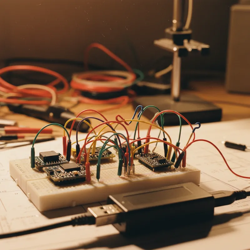
A practical peripheral-validation pass with the Pulsar looks like this. Bring up the board on its own supply, then use the Pulsar’s programmable downstream power only for isolated peripheral rails during early bring-up. Scan I2C and confirm every expected device answers at its documented address. Read the SPI flash JEDEC ID, then read back the calibration region and diff it against the golden image. Open the UART console and drive the ECU through its state machine while watching for the messages that should accompany each transition. Where an RS-485 link exists, capture idle traffic before injecting anything, so you know what normal looks like. Use the six GPIO pins for resets and enables so the whole sequence can be repeated without touching the board.
Every one of those steps is scriptable through Binho’s Python SDK, which is what turns a bring-up checklist into a regression that runs on every hardware revision.
Why Buy from GSAS
GSAS Micro Systems is an authorized Binho engineering partner in India. We provide the Pulsar with INR invoicing and local support for automotive engineering teams. Our applications engineers in Bengaluru, Hyderabad, Chennai, Pune, Mumbai, and Delhi NCR assist with SPI, I2C, UART and RS-485 bring-up, Python scripting for automated test sequences, and honest scoping of which Binho instrument fits your validation plan and which does not yet. Contact us for evaluation units or a technical consultation.
Also appears in:
Interested in Binho tools?
Talk to our application engineers for personalized tool recommendations.
More from Binho
View all →
I3C FAQ for Firmware Teams: What the Bus Is, What Changes, and What You Need on the Bench
31 Jul · 8 min
Running the Binho Supernova as an I3C Target: Emulating a Device Against Your Own Controller
31 Jul · 7 min
Binho Mission Control 3 (Public Preview): Point-and-Click I2C, SPI, I3C, and GPIO
20 Jul · 5 min
Binho Mission Control: Point-and-Click I2C, SPI, and UART Without Writing Code
7 Apr · 5 min

Emulating Processor Power for Thermal Testing: Why Constant Power
7 Oct · 7 min

CRPS and Rack Power Supply Testing: The Six Tests That Matter
7 Oct · 7 min


