
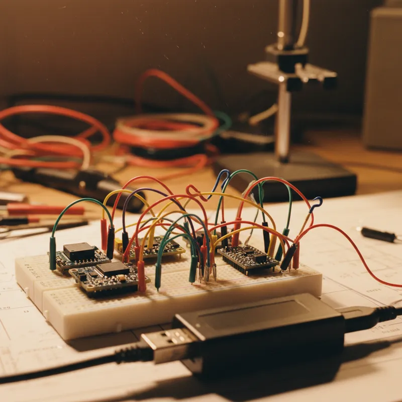
Binho Mission Control: Point-and-Click I2C, SPI, and UART Without Writing Code
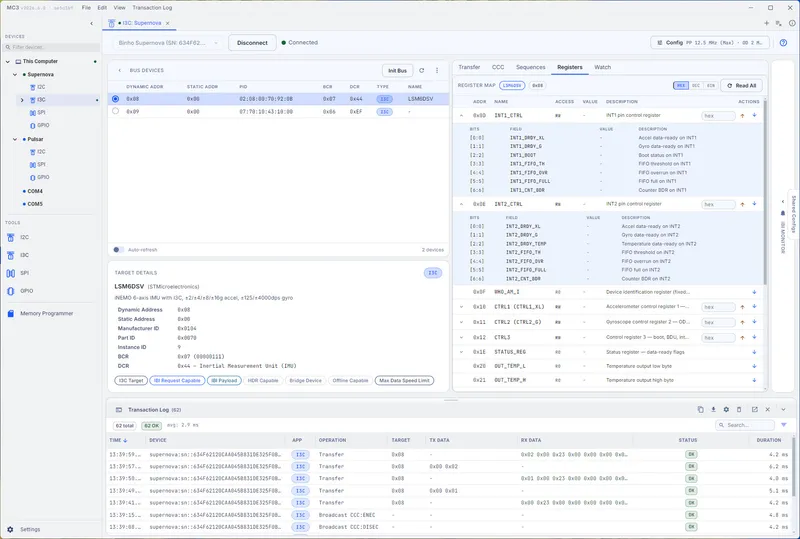
Update (July 2026): Binho has released Mission Control 3 in Public Preview, a ground-up rebuild with a single workbench for I2C, SPI, I3C, and GPIO plus a visual memory programmer. Mission Control 3 supports the Supernova and Pulsar; the walkthrough below covers Mission Control 2, which continues to power the Nova.
The first thing most engineers want to do with a new sensor, PMIC, or communication module is talk to it, send a register read, see if it responds, check the device ID, verify that the bus is alive. Before writing firmware, before setting up a development environment, before committing to a schematic, they want proof that the silicon does what the datasheet says.
Binho’s Mission Control software provides exactly this capability for the Binho Nova and Binho Supernova. It is a cross-platform GUI application (Windows, macOS, Linux) that lets engineers interact with I2C, SPI, UART, and I3C buses through a graphical interface, no code required.
I2C Bus Scanning
Mission Control’s I2C scanner is often the first feature engineers use. It scans all 112 valid I2C addresses (0x08 through 0x77) and reports which addresses acknowledge. For a new board that just came back from the fabricator in Chennai or Pune, this scan answers the fundamental question: are the I2C devices present and responding?
The scan takes a few seconds and displays results in a grid view showing acknowledged addresses highlighted. From there, the engineer can select any responding address and perform individual register reads and writes through the GUI. Enter the register address, click Read, and the register value appears. Change a value, click Write, and the new value is sent.
This interactive register access is invaluable during board bring-up. An engineer verifying a TMP117 temperature sensor can read the Device ID register (0x0F) to confirm the silicon is genuine, read the temperature register (0x00) to see if the sensor is returning a plausible value, and modify configuration registers to test different operating modes, all without writing a single line of firmware.
SPI Transfers
Mission Control’s SPI interface provides the same interactive capability for SPI buses. The engineer configures the SPI mode (clock polarity and phase), clock speed, chip select behavior, and byte order, then sends and receives data through a hex entry field.
For SPI flash operations, reading a JEDEC ID, erasing a sector, programming data, Mission Control provides the raw SPI transaction mechanism. The engineer sends the JEDEC ID command (0x9F) and reads back the manufacturer and device ID bytes. For a Winbond W25Q128 flash on a new PCB, seeing the expected response (0xEF, 0x40, 0x18) confirms that the flash is connected, powered, and responding to SPI commands.
Mission Control also supports multi-byte SPI transactions for reading and writing flash pages, making it practical for small-scale data recovery, firmware extraction, and flash content verification during debug sessions.
UART Monitoring and Injection
The UART interface in Mission Control functions as a serial terminal with hex and ASCII display modes. Engineers connect to a device’s UART output (debug console, GPS NMEA stream, sensor data output) and see the data in real time. The interface supports configurable baud rates, data bits, parity, and stop bits.
For firmware teams, this replaces the USB-to-UART adapter and separate terminal emulator that would otherwise be needed for serial console access. The Binho Nova or Supernova handles both the protocol bus work (I2C, SPI) and the serial console monitoring through a single USB connection.
Data injection allows the engineer to send commands to the target device through UART, useful for devices with AT command interfaces, CLI-based configuration, or custom serial protocols.
I3C Support (Supernova Only)
For the Binho Supernova, Mission Control extends to MIPI I3C. The I3C interface provides dynamic address assignment, in-band interrupt monitoring, HDR-DDR data transfers, and CCC (Common Command Code) execution through the GUI.
This is where Mission Control provides capability that simply does not exist elsewhere in a GUI tool. Engineers working on I3C sensor hubs, camera interface modules, or next-generation PMICs can interact with the I3C bus interactively, discovering devices, assigning addresses, reading status, and transferring data, without writing I3C driver code or building FPGA-based test fixtures.
Bus Monitoring and Protocol Decoding
Beyond interactive transactions, Mission Control provides bus monitoring that captures and decodes protocol traffic in real time. For I2C, this shows each transaction with address, direction, data bytes, and ACK/NACK status. For SPI, it shows MOSI/MISO data with chip select timing. For UART, it shows timestamped data streams.
This monitoring capability turns the Binho adapter into a lightweight protocol analyzer. While it does not replace a dedicated logic analyzer with deep memory and complex triggering, it provides sufficient visibility for the vast majority of debug scenarios, confirming that a device is responding correctly, identifying communication errors, and verifying protocol timing.
Scripting Bridge
Mission Control serves as a stepping stone to automated workflows. Once an engineer has interactively validated a bus configuration and protocol sequence, they can replicate that sequence in Python using Binho’s SDK. The GUI work identifies the correct register addresses, command sequences, and timing parameters; the Python script automates them for repeatable execution.
Scripts developed on the Nova transfer directly to the Supernova and Binho Pulsar without modification, the Python SDK provides a common API across all Binho adapters.
Cross-Platform Availability
Mission Control runs natively on Windows, macOS, and Linux. For engineering teams in Bengaluru and Hyderabad where developers use a mix of operating systems, Windows for EDA tools, macOS for firmware development, Linux for CI servers, the cross-platform support means the same tool and the same workflow work everywhere.
Why Buy from GSAS
GSAS Micro Systems is an authorized Binho engineering partner in India. We provide the Nova, Supernova, and Pulsar with INR invoicing and local technical support. Our applications engineers in Bengaluru, Hyderabad, Chennai, Pune, Mumbai, and Delhi NCR help teams get started with Mission Control and transition to Python-scripted automation as their workflows mature. Contact us for evaluation units or a hands-on demo.
Also appears in:
Interested in Binho tools?
Talk to our application engineers for personalized tool recommendations.
More from Binho
View all →
I3C FAQ for Firmware Teams: What the Bus Is, What Changes, and What You Need on the Bench
31 Jul · 8 min
Running the Binho Supernova as an I3C Target: Emulating a Device Against Your Own Controller
31 Jul · 7 min
Binho Mission Control 3 (Public Preview): Point-and-Click I2C, SPI, I3C, and GPIO
20 Jul · 5 min
From Dedicated Analyzers to Multi-Protocol USB Adapters: A Bench Tool Evolution
7 Apr · 5 min

Emulating Processor Power for Thermal Testing: Why Constant Power
7 Oct · 7 min

CRPS and Rack Power Supply Testing: The Six Tests That Matter
7 Oct · 7 min


