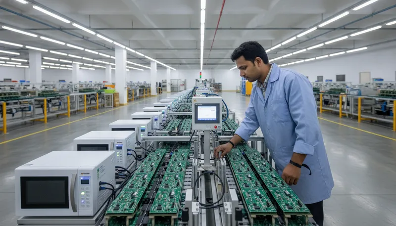
India’s electronics manufacturing services (EMS) sector is in the middle of the largest capacity build-out in its history. Syrma SGS, Kaynes Technology, Avalon Technologies, Rangsons, Centum Electronics, Bharat FIH, and the Tier-2 contract manufacturers supplying automotive OEMs in Pune, Chennai, and Bengaluru are all scaling up. And every one of those lines runs into the same bottleneck sooner or later: programming the microcontroller on the assembled board quickly, reliably, and without exposing the customer’s plaintext firmware to the factory floor.
This is where SEGGER’s Flasher ATE2 and Flasher Hub production programmers earn their keep. This post walks through what Flasher ATE2 actually is, how it integrates into the kind of ICT (in-circuit test) bench Indian EMS lines already run, how the 10-up gang-programming throughput works out against typical Indian build volumes, and what traceability hooks exist for OEM customers filing under ISO 13485 (medical), IATF 16949 (automotive), and DGQA / iDEX (defence). GSAS Micro Systems is an authorized SEGGER partner, every Flasher variant is available with INR invoicing and on-site bring-up support at EMS lines in Bengaluru, Pune, Chennai, Hyderabad, Mumbai, Delhi NCR, and Noida.
What Flasher ATE2 actually is
Flasher ATE2 is a rack-mounted production programmer built around SEGGER’s mature J-Flash device database (the same one that powers J-Link, which means the flash algorithm validated on the bench is byte-identical to the algorithm running on the line). Mechanically, a Flasher ATE2 system is a main board plus up to 10 module boards stacked in a single enclosure, each module programming one device under test (DUT) in parallel. Dedicated Ethernet interface. Open-drain target power control. Dedicated GPIO handshake lines for ATE integration. Programmed image payloads uploaded over FTP from manufacturing engineering to the rack before a shift starts.
For an Indian EMS line programming Cortex-M MCUs, STM32, NXP i.MX RT, Nordic nRF52/nRF53, Renesas RA, Microchip SAM, Silicon Labs, Raspberry Pi RP2040/RP2350, the 10-up parallel architecture collapses per-unit programming time by close to the channel count. A 512 KB image that takes 7 seconds on a single J-Link programs 10 boards in 7 seconds on a Flasher ATE2, not 70. That is the difference between a 5,140 units/hour line and a 514 units/hour line on the same image, on the same silicon, with no change to the test fixture downstream.
For lower-volume Indian defence, medical, and railway production, where the mix is high and the volume per SKU is moderate, the Flasher Hub-4 and Flasher Hub-12 variants are the right answer. The Hub-12 gives you 12 independent channels that can run the same image across all targets or different images on each target, with lower upfront cost than the ATE2 rack. Hub configurations fit naturally into the small-batch electronics production lines common in Indian defence supply chains (under iDEX) and medical device contract assembly.
Power topology: the one thing Indian test-fixture engineers get wrong on first build
The SEGGER Flasher ATE and ATE2 documentation (AN08007) specifies the target power pin (nTPWR) as an open-drain control, not a power supply. This is a load-bearing detail that Indian test-fixture engineers have historically gotten wrong on first build, because most competing programmers deliver target VCC from the programmer side and the reflex is to wire nTPWR the same way.
The correct topology is that your ICT bench supplies the DUT from its own benchtop power, and Flasher ATE2’s nTPWR pin pulls LOW when the programmer needs the target live and RELEASES (high-impedance) when the programmer is idle. Your test bench latches the DUT power accordingly. This decoupling matters because a single Flasher ATE2 rack often programs boards that each have their own legitimate supply requirements (an STM32L4 sensor node at 3.3 V, an i.MX RT1170 gateway at 5 V with independent 1.8 V core rails, a Nordic nRF52 board powered through a boost converter from a battery fixture), forcing all of them to share a programmer-supplied rail is the path to a ground-loop incident.
The payoff of getting this right once is that the same Flasher ATE2 rack then works across every board your line programs, with no hardware change between builds. Your manufacturing engineering team just swaps J-Flash project files for the new image.
Integration with Indian ICT benches: SPEA, Teradyne, JTAG Technologies, and home-grown fixtures
Flasher ATE2 exposes two independent drive modes for integration with automated test equipment:
-
ASCII commands over TCP. The programmer accepts simple text commands (
#AUTO,#START,#STATUS,#BATCH <id>) over a dedicated TCP port. This is the right fit for modern ICT benches that have a full Python or C# test stack, including the SPEA 3030 and home-grown Raspberry-Pi-based fixtures that several Indian mid-tier EMS houses use for lower-volume products. A 20-line Python script on the ICT controller is all it takes to drive a Flasher ATE2 rack between test phases. -
Dedicated handshake lines. For ATE equipment without a TCP stack (some legacy Teradyne and JTAG Technologies controllers still running under VxWorks or dedicated Windows test programs), Flasher ATE2 exposes one GPIO per control line. Start, busy, done, pass, fail are all available as discrete signals with configurable polarity. Indian lines running older test executives can integrate Flasher ATE2 as a “drop-in gang programmer” without rewriting the test sequence software.
Both modes work identically on Flasher Hub-4 and Flasher Hub-12 variants, so an EMS that standardizes on the hub-class programmer for its lower-volume lines can use the same integration stack for its higher-volume ATE2 lines.
MES integration and traceability: the piece that matters for OEM audits
This is the section every Indian EMS engineering manager should read twice, because it is the part that decides whether a new OEM customer will actually ship product through your facility.
Flasher ATE2 produces a per-unit programming record for every board it programs, the target serial number (read from the MCU’s unique device ID), the image hash, the programming timestamp, the programmer serial, and pass/fail status. This record is the raw material for MES traceability. The line’s Manufacturing Execution System can consume it either by polling the Flasher ATE2 over TCP or by parsing the optional CSV log that the programmer emits over its Ethernet interface.
For Indian OEMs with serious traceability requirements, medical devices under CDSCO / ISO 13485, automotive Tier-1s under IATF 16949, defence programs under DGQA, this MES integration is not optional. It is the ingress point for the device history record, and the audit trail has to be consistent with the rest of the manufacturing data stream. A Flasher ATE2 deployed cleanly into an MES saves the OEM a painful compliance retrofit later.
For lower-complexity products (consumer IoT, lighting, white goods, appliances) the same traceability data is still useful, it becomes the substrate for warranty claim analysis and field-failure correlation.
When to step up to Flasher Secure
Flasher ATE2 programs plaintext firmware. For many Indian products that is fine. For a growing share of product categories, automotive ECUs, medical devices, industrial control with customer-IP-owned firmware, and anything touching defence, the programming step must not expose the plaintext to the contract manufacturer.
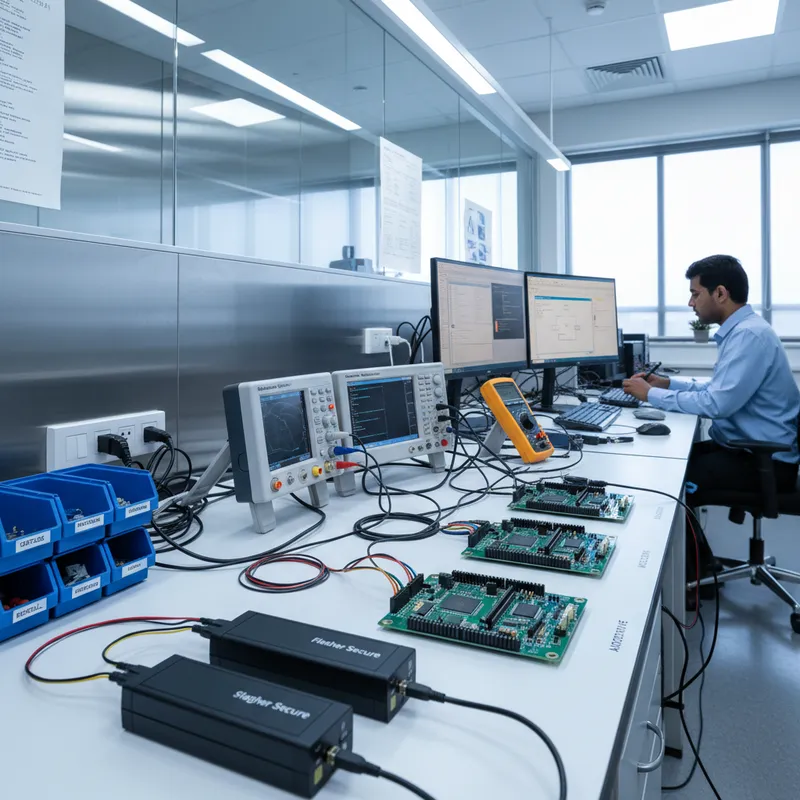
This is where Flasher Secure comes in. Flasher Secure pairs with a Flasher Secure Server (FSS) hosted at the IP owner’s premises. The IP owner signs the image, uploads it to FSS, and issues a bounded number of programming authorizations (say, 5,000 units per month). The Flasher Secure on the CM floor consumes one authorization per programmed unit. Any attempt to over-run the authorization count produces hardware that will not boot. The plaintext firmware never leaves the IP owner’s premises, only authorized programming events do.
For Indian defence programs under iDEX and DGQA, Indian medical OEMs filing with CDSCO, and Indian automotive Tier-1s shipping to customers with strict firmware-provenance requirements, Flasher Secure is increasingly a compliance requirement rather than an optimization. GSAS engineers can help bring up a Flasher Secure deployment with FSS in the OEM’s Bengaluru or Pune R&D centre and Flasher Secure racks on the CM’s Chennai or Noida floor in under a day.
Silicon support matrix: what Flasher ATE2 actually programs
Flasher ATE2 supports the same device database as J-Link. Practically, this means every silicon family that is currently shipping into Indian production:
- STMicroelectronics STM32: every STM32 F/G/H/L/U/WB/WL/WBA variant, plus the newer STM32H5 and STM32N6 lines
- NXP i.MX RT: RT500, RT600, RT1010/1020/1050/1060/1170, including external Octo-SPI and Hyper-Flash programming via the boot ROM handshake
- NXP Kinetis, MCX, and S32K automotive families
- Nordic Semiconductor: nRF52, nRF53, nRF54L, nRF9160/9161 LTE-M (including the network core on nRF5340)
- Renesas: RA family (Arm Cortex-M), RX family (via a dedicated Flasher RX variant), RH850 automotive (via the J-Link RH850 adapter for development, Flasher ATE2 support for RH850 is limited; consult SEGGER directly for automotive RH850 programming workflows)
- Infineon: PSOC 4/5/6/61/62/63, XMC1/XMC4
- Microchip / Atmel: SAM family (Cortex-M), PIC32
- Silicon Labs: EFM32, EFR32 (BLE, Zigbee, Matter, Thread)
- Raspberry Pi: RP2040, RP2350 (both Arm and RISC-V modes)
- GigaDevice: GD32 (Chinese Cortex-M + RISC-V variants popular with Indian EV and consumer cost-sensitive designs)
- WCH: CH32V RISC-V (cost-sensitive IoT and hobbyist-derived commercial products)
- Espressif ESP32 (RISC-V cores on C3/C6/S3)
If your Indian EMS line programs across multiple MCU vendors across different customer builds, which is common, a single Flasher ATE2 rack handles all of them, no hardware swap required. Only the J-Flash project file changes between builds.
Deployment path: from evaluation to line-live
The typical GSAS engagement on Flasher ATE2 follows this sequence:
- Evaluation. GSAS lends a single-module Flasher Compact or a small Flasher Hub-4 to the EMS engineering team for two weeks of trial programming against the customer’s actual board. This catches any fixture-design surprises before commitment.
- Pilot. The EMS team runs a small pilot production batch (typically 500-2,000 units) with the pilot Flasher hardware in the existing ICT bench, validating the MES integration and OEM traceability handoff.
- Line-live purchase. The EMS commits to the Flasher ATE2 or Flasher Hub-12 rack for the production line. GSAS handles INR invoicing, GST, and local delivery. Bring-up engineering on-site at the customer’s Indian EMS facility is included.
- Secure provisioning (optional second phase). If the OEM customer requires encrypted-image programming, the same line adds a Flasher Secure pairing with an FSS instance at the OEM’s R&D centre. GSAS supports both sides of the deployment.
Further reading
- SEGGER Flasher ATE Production Programmer Getting Started (AN08007), the authoritative SEGGER bring-up reference
- SEGGER Knowledge Base, Flasher ATE2 Getting Started, supplementary step-by-step guide
- Flasher Secure, authorized flashing technology, for encrypted firmware programming
- SEGGER Flasher product family page, full catalog
- GSAS SEGGER partnership overview
- J-Link models for bench development that feed into Flasher production
Interested in SEGGER tools?
Talk to our application engineers for personalized tool recommendations.
More from SEGGER
View all →
Meet the GSAS Team at electronica India 2026, Stall H3.I45
15 Sept · 3 min
J-Link Is Now Validated by ST for StellarStudio
13 Sept · 2 min

An AI Agent That Drives the Debugger: SEGGER and Embedder Connect J-Link to the Loop
13 Sept · 6 min
SEGGER J-Link and J-Trace Now Support Andes Trace: Why This Matters for RISC-V
21 Jul · 6 min

Emulating Processor Power for Thermal Testing: Why Constant Power
7 Oct · 7 min

CRPS and Rack Power Supply Testing: The Six Tests That Matter
7 Oct · 7 min