
Every embedded developer eventually hits the wall: you are chasing a bug through a driver, an RTOS task, and two interrupt handlers, and the debugger refuses the next breakpoint. The silicon is the limit. SEGGER puts the figures plainly: 2 hardware breakpoint units on ARM7/9 and 4 to 6 on Cortex-M, and that is all the chip has.
Unlimited Flash Breakpoints is SEGGER’s answer, and it is one of the most misunderstood features in the J-Link family, both in how it works and in which models actually include it. Both halves matter when you are choosing a probe.
The problem: breakpoints in flash are hard
A software breakpoint is simple in RAM: the debugger swaps an instruction for a breakpoint instruction and puts the original back later. Code executing in place from flash resists that trick, because flash is not byte-writable; changing one instruction means erasing and reprogramming a whole sector.
So debuggers normally fall back on the hardware comparators, all four-to-six of them. Complex debugging sessions, conditional-path hunting, and library-heavy codebases run out fast. And there is a second, less-known ceiling SEGGER documents: on most Cortex-M3 and Cortex-M4 devices, hardware breakpoints cannot be set in external memory at all, so firmware running from memory-mapped external flash can be undebugable with hardware units alone.
How J-Link does it
SEGGER’s technology takes the flash-reprogramming route and makes it practical. Per SEGGER’s documentation:
- “The J-Link software reprograms a flash sector to set or clear a breakpoint.”
- “Flash sectors are programmed only when necessary, typically when execution of the target program is started.” Setting ten breakpoints in the same sector costs one reprogram, not ten.
- “A built-in instruction set simulator further reduces the number of required flash operations.” Where J-Link can simulate the instructions around a breakpoint, it avoids touching the flash at all.
The result, in SEGGER’s words, “minimizes delays for the user while maximizing the lifetime of the flash”, and “on microcontrollers with fast flash, the difference between breakpoints in RAM and in flash is hardly noticeable”. In day-to-day use, you set breakpoints in the IDE as if the limit did not exist; the probe handles the rest transparently.
It also reaches where hardware comparators cannot: SEGGER states the feature works “in both internal and external flash, including memory-mapped QSPI flash”, which is exactly the memory hardware breakpoints abandon on most Cortex-M3/M4 parts.
Which J-Link models include the license
This is where teams get caught, and it is worth quoting SEGGER directly: “For all J-Trace and J-Link models higher than J-Link BASE, the Unlimited Flash Breakpoints feature is included”, and “J-Link BASE requires an upgrade BASE to PLUS.”
| Probe | Unlimited Flash Breakpoints |
|---|---|
| J-Link BASE / BASE Compact | Not included; requires the BASE-to-PLUS upgrade |
| J-Link PLUS | Included (license preinstalled with J-Flash, Ozone, RDI) |
| J-Link ULTRA | Included |
| J-Link PRO / PRO PoE | Included |
| J-Link WiFi | Included |
| J-Link EDU Mini | Included, education-only license |
| J-Link OB | Standard OB matches BASE; the OB PLUS option adds it |
Two practical notes. First, the BASE-to-PLUS upgrade is a software license for a probe you already own, and it bundles more than breakpoints: J-Flash and J-Flash SPI, the Ozone debugger, monitor-mode debugging, and RDI come with it. Second, SEGGER offers a free 30-day trial license, requested by emailing your J-Link serial number to SEGGER, so a team on BASE probes can evaluate the workflow before buying the upgrade.
If you are still choosing a probe, the arithmetic is usually simple: the moment your debugging style wants more than a handful of breakpoints, the J-Link PLUS with everything preinstalled is the cleaner buy than BASE plus a later upgrade. Our J-Link buyer’s guide and PRO vs ULTRA comparison cover the rest of the decision.
Get flash breakpoints working in India
GSAS Micro Systems is an authorized SEGGER engineering partner in India. We supply every J-Link model and the BASE-to-PLUS upgrade with competitive pricing and short lead times, INR invoicing, and GST documentation, and our field application engineers in Bengaluru, Hyderabad, Chennai, Pune, Mumbai, and Delhi NCR help teams set up their debug workflows end to end.
Request a quote, or explore the full SEGGER portfolio at GSAS.
Also appears in:
Interested in SEGGER tools?
Talk to our application engineers for personalized tool recommendations.
More from SEGGER
View all →
Meet the GSAS Team at electronica India 2026, Stall H3.I45
15 Sept · 3 min
J-Link Is Now Validated by ST for StellarStudio
13 Sept · 2 min

An AI Agent That Drives the Debugger: SEGGER and Embedder Connect J-Link to the Loop
13 Sept · 6 min
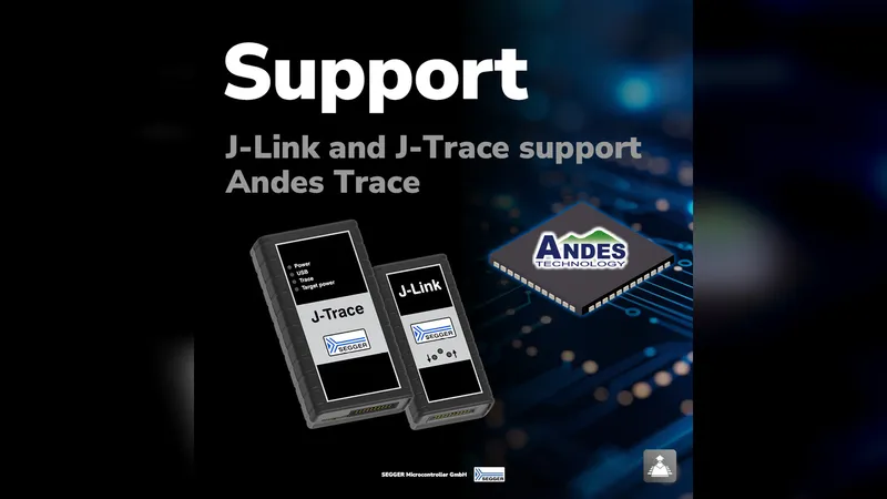
SEGGER J-Link and J-Trace Now Support Andes Trace: Why This Matters for RISC-V
21 Jul · 6 min

Emulating Processor Power for Thermal Testing: Why Constant Power
7 Oct · 7 min

CRPS and Rack Power Supply Testing: The Six Tests That Matter
7 Oct · 7 min


