
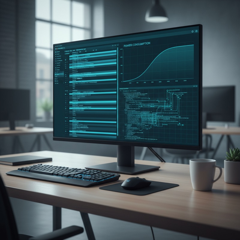
Measuring how much current a device draws is straightforward. Understanding why it draws that current at a specific moment requires correlating power measurements with code execution, knowing which function was running, which peripheral was active, and which RTOS task was scheduled when a power spike occurred. SEGGER Ozone provides this through its Timeline window, which synchronizes power data with code-level execution on a common timescale.
Three Synchronized Panes
Ozone’s Timeline combines three panes sharing the same horizontal time axis:
Data pane. Displays sampled variable values over time. Any global variable, peripheral register, or memory location can be added as a channel, shown as a line graph. Useful for tracking state machines, buffer levels, ADC readings, or GPIO states alongside power.
Power pane. Shows device current consumption over time via the J-Link’s built-in power measurement. Current appears as a continuous waveform, sleep mode entry, peripheral activation, radio transmit bursts, and LED toggling are all visible. A single LED toggle adds roughly 6 mA of step change, providing a clear visual marker.
Code pane. Displays which code was executing at each point in time. With ETM or PTM trace data, it shows the exact program counter history, every function call, branch, and interrupt. This transforms a power measurement from “something happened at time T” into “function X in task Y was executing at time T.”
Because all panes share one timescale, clicking a power spike scrolls Code and Data to the same moment. You see current draw, executing code, and variable state simultaneously.
J-Link vs J-Trace PRO
The panes have different hardware requirements:
Data + Power (J-Link). Any J-Link with power measurement populates the Data and Power panes. J-Link samples variables through background memory access and reads current through its measurement circuit, no additional hardware needed.
Code (J-Trace PRO). Full continuous instruction trace requires a J-Trace PRO connected to the target’s ETM trace port. J-Trace PRO captures the complete instruction stream, streamed to Ozone over USB or optionally Gigabit Ethernet for sustained sessions.
Without J-Trace PRO, the Code pane shows sampled PC values, statistical profiling rather than continuous trace. For power work, continuous trace tells you that the 15 mA spike at T=1.234s was caused by a specific TX function in a specific task. Sampled PC only tells you 40% of time is spent in the radio driver.
Practical Workflow
-
Connect. Attach J-Link or J-Trace PRO. Open Timeline, add the Power channel and any Data channels for system state variables.
-
Record. Run the system through operating scenarios, active processing, idle, communication bursts, sleep transitions.
-
Navigate. Zoom and scroll to power events of interest. Click a spike to see Code and Data at that moment.
-
Correlate. Does current spike every time a specific task runs? Does the device fail to enter sleep after a particular function? Is a peripheral left enabled too long?
-
Optimize. Modify firmware, re-record, compare. The Timeline makes it visible whether your change reduced consumption.
Example: Task Switch Correlation
A system with three tasks, sensor, communication, idle (sleep mode). The Power pane shows a repeating pattern: low current (sleep), brief spike (sensor), low current, longer spike (communication), low current.
With Code trace, you verify the idle task actually enters low-power sleep (not a busy-wait consuming full run current). You measure microseconds between sleep entry and wake-up interrupt. You see whether communication enables the radio before data is ready, wasting current during preparation. None of these insights come from power measurement or code debugging alone, only from correlation.
Power Profiling Tools in India
GSAS Micro Systems provides Ozone, J-Link, and J-Trace PRO with INR invoicing and local engineering support. Teams in Bengaluru, Chennai, Hyderabad, Pune, Mumbai, and Delhi NCR can get assistance with setup, configuration, and power optimization workflows.
Also appears in:
Interested in SEGGER tools?
Talk to our application engineers for personalized tool recommendations.
More from SEGGER
View all →
Meet the GSAS Team at electronica India 2026, Stall H3.I45
15 Sept · 3 min
J-Link Is Now Validated by ST for StellarStudio
13 Sept · 2 min

An AI Agent That Drives the Debugger: SEGGER and Embedder Connect J-Link to the Loop
13 Sept · 6 min
SEGGER J-Link and J-Trace Now Support Andes Trace: Why This Matters for RISC-V
21 Jul · 6 min

Emulating Processor Power for Thermal Testing: Why Constant Power
7 Oct · 7 min

CRPS and Rack Power Supply Testing: The Six Tests That Matter
7 Oct · 7 min


