
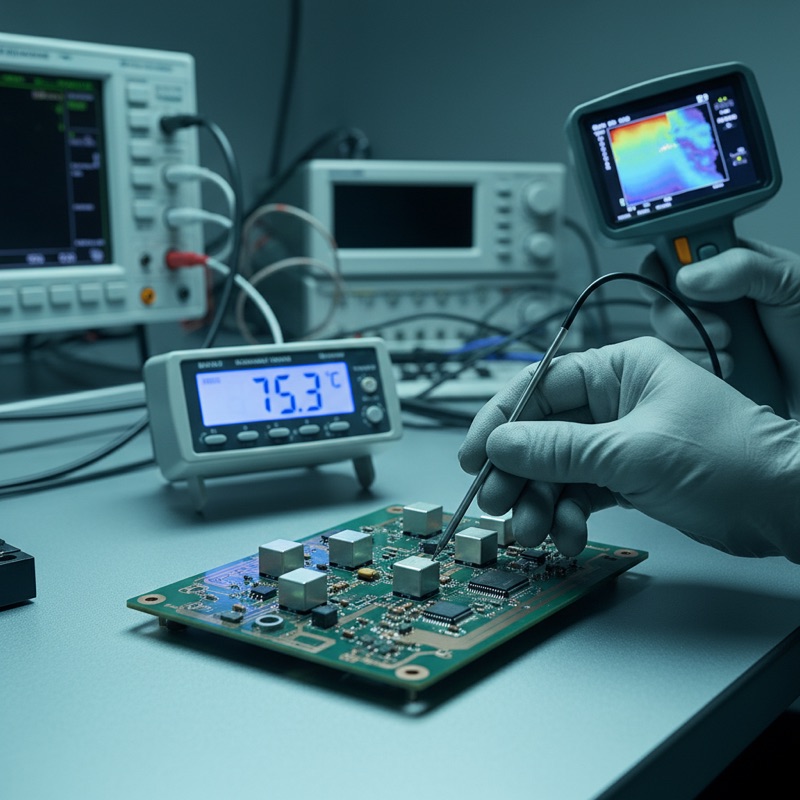
Power inductors have two current ratings that define their operating envelope. The first is Isat, the saturation current at which inductance drops below a specified threshold. The second is Irms, the RMS current that causes a specified temperature rise above ambient, typically 40 degrees C. In many power inductor designs, Irms is the more restrictive limit. And in electric vehicle power electronics, where inductors operate in thermally constrained enclosures under sustained load, Irms determines whether the inductor survives the application.
What Irms Represents
When DC current flows through an inductor’s winding, power is dissipated as I-squared-R loss in the copper. This heat raises the inductor’s temperature above ambient. The temperature rise depends on the current magnitude, the DC resistance of the winding, and the inductor’s thermal impedance, its ability to conduct and radiate heat to the surrounding environment.
Irms is the current at which the inductor reaches a defined temperature rise limit. Unlike Isat, which is a magnetic parameter, Irms is a thermal parameter. An inductor can be well below its saturation limit and still exceed its thermal rating if the winding resistance generates excessive heat.
In EV applications, this distinction is critical. A DC-DC converter inductor in a battery management system or on-board charger operates at high current for extended periods, not the transient bursts that desktop power supplies see, but sustained load during highway driving or fast charging. The thermal limit dominates.
How Microtest Measures Irms
The Microtest DC Bias Current Test System measures Irms using the copper temperature coefficient method. The approach is straightforward in concept and rigorous in execution.
Copper has a well-characterized, repeatable temperature coefficient of resistance, approximately 0.393% per degree C. As an inductor heats up under DC current, its winding resistance increases. By measuring DCR at a known reference temperature and then monitoring DCR as the inductor carries current, the system calculates the winding’s temperature rise without requiring an external temperature sensor.
This method evaluates thermal performance objectively. It measures the winding temperature directly, avoiding the inaccuracies of surface-mounted thermocouples that read case temperature rather than hotspot temperature. The difference between case and winding temperature can be significant in potted or encapsulated inductors where thermal gradients exist between the copper and the outer surface.
Why Irms Matters for EV Power Electronics
Electric vehicles use power inductors in several subsystems, each with thermal demands:
Battery management systems. Cell balancing circuits and DC-DC converters that step battery voltage to auxiliary rails carry continuous current during vehicle operation. Inductor temperature rise directly affects enclosure thermal budgets.
Inverter DC-link filters. The DC bus filter between the battery and traction inverter smooths current ripple. These inductors handle high RMS currents with significant harmonic content, demanding Irms characterization that accounts for AC losses in addition to DC heating.
DC-DC converters. The high-voltage to low-voltage converter (typically 400V or 800V bus down to 12V or 48V auxiliary) operates continuously. Inductor Irms rating must support maximum load current at maximum ambient temperature with margin.
On-board charger. During charging, the PFC inductor and output filter inductor carry sustained current for 30 minutes to several hours. Temperature rise accumulates over the charging session, and Irms must account for worst-case conditions.
DCR as the Bridge Between Electrical and Thermal
DCR measurement is integral to Irms characterization. The Microtest DC Bias systems, both the 6632+ and 6350+ platforms, include built-in DCR measurement technology. This serves two purposes: it provides the baseline resistance value for I-squared-R loss calculations, and it enables the temperature coefficient method for Irms determination.
For EV inductor manufacturers, DCR is also a production quality metric. Winding resistance variations between units indicate winding process inconsistencies, wire gauge errors, turn count errors, or termination resistance variations, that affect both thermal performance and lot-to-lot consistency.
Long-Duration Testing
EV inductor qualification often requires extended thermal testing, running the inductor at rated current for hours to verify thermal equilibrium. The Microtest system supports long-term consecutive maximum power output, enabling sustained bias current delivery for the duration needed to reach thermal steady state. This is not a quick production test, it is an engineering characterization that builds the evidence base for component qualification.
The Dual Rating Approach
A complete inductor characterization for EV applications requires both Isat and Irms data. The Microtest DC Bias system provides both in a single test platform, Isat scanning reveals the magnetic saturation limit, Irms scanning reveals the thermal limit, and DCR measurement provides the resistive loss baseline. The lower of the two current ratings sets the application limit, and knowing both enables optimized inductor selection where neither margin is wasted.
Availability in India
GSAS is an authorized engineering partner in India, providing the 6632+ and 6350+ DC Bias systems with applications support for EV power electronics testing. Our team serves inductor manufacturers, power electronics designers, and automotive Tier-1 suppliers across Bengaluru, Hyderabad, Chennai, Pune, Mumbai, Delhi NCR, and Visakhapatnam.
Also appears in:
Interested in Microtest tools?
Talk to our application engineers for personalized tool recommendations.
More from Microtest
View all →
Power Measurement for Server PSUs: Microtest 7140 Power Analyzer
7 Apr · 5 min

Wireless Charger QC Testing with the Microtest 9901
7 Apr · 5 min
Motor Stator Testing in EV Manufacturing: Microtest MT-6910 Series
7 Apr · 5 min
PCB Incoming Inspection with Multichannel LCR Testing
6 Apr · 5 min

Emulating Processor Power for Thermal Testing: Why Constant Power
7 Oct · 7 min

CRPS and Rack Power Supply Testing: The Six Tests That Matter
7 Oct · 7 min


