In short
The Arm Cortex-M4 is a 32-bit RISC processor implementing the Armv7E-M architecture profile, the DSP-extended variant of Armv7-M used by the Cortex-M3. It runs only Thumb-2 instructions on a 3-stage fetch, decode and execute pipeline, adds SIMD and saturating-arithmetic DSP instructions over the Cortex-M3, and offers an optional single-precision floating-point unit.
If you are an Indian embedded engineer who has shipped a BLDC controller, an energy meter, or a wearable sensor node, chances are the silicon underneath was built around an Arm Cortex-M4 core. The Cortex-M4 has become the workhorse of mid-range Indian embedded product design, powerful enough to run DSP in real time, low-power enough to live on a coin cell, and cheap enough to hit a tight BOM. This deep dive unpacks the Cortex-M4 architecture for engineers who have to defend a silicon choice in a design review. It is also the architectural reference we lean on when Indian customers pick up Arm Keil MDK through GSAS Micro Systems, Arm’s authorized partner in India for Arm Development Tools.
This is a reference article, not a comparison piece. We cover pipeline and bus structure, DSP extensions, the optional FPU, memory map and bit-banding, NVIC low-latency interrupts, the MPU for RTOS isolation, CoreSight debug, a Cortex-M3 / M4 / M7 comparison, and the arm cortex microcontrollers from silicon vendors that Indian engineers encounter in the field.
Arm Cortex-M4 Architecture: Core Pipeline and Bus Structure
The Arm Cortex-M4 is a 32-bit RISC processor implementing the Armv7E-M architecture profile, the DSP-extended variant of Armv7-M. Armv7-M is the baseline microcontroller profile used by Cortex-M3. Armv7E-M extends it with DSP instructions (SIMD, saturating arithmetic) and is used by Cortex-M4 and Cortex-M7. Both profiles share a single execution state in which the core only runs Thumb-2 instructions. There is no legacy 32-bit Arm (A32) state on the Cortex-M4, which gives one of the most code-dense instruction sets Arm ships, the reason a typical Indian product can fit in 128 KB or 256 KB of flash.
The pipeline is short and predictable: a classic 3-stage Fetch → Decode → Execute. Branch prediction is intentionally minimal. Branches resolve in execute and the pipeline refills on a taken branch, the right trade-off for a deterministic real-time microcontroller. The core also supports single-cycle 32×32 integer multiply and an early-terminating 32÷32 divider.
The bus structure is harvard-ish and exposes four buses:
- I-bus (instruction bus): fetches code from the Code region (
0x00000000–0x1FFFFFFF), typically internal flash. - D-bus (data bus): performs data loads and stores to the Code region. Separate I-bus and D-bus mean an instruction fetch and a literal-pool load can happen in the same cycle.
- S-bus (system bus): handles SRAM (
0x20000000), peripheral (0x40000000), external RAM, and external devices. - PPB (private peripheral bus): a dedicated bus to core peripherals at
0xE0000000: NVIC, SysTick, MPU, SCB, debug.
This split is why Cortex-M4 firmware can sustain flash-accelerated execution while hitting SRAM for the working set, the fetch engine is not competing with the data path. For a 20 kHz PWM loop in SRAM running a control law out of flash, that is the difference between fitting the sample window and missing it.
The Cortex-M4 also supports unaligned data access in hardware (a uint32_t at an odd address reads in a single LDR), and exposes a SysTick timer, a 24-bit down-counter that every RTOS uses as its tick source.
DSP Extensions and the SIMD Instruction Set
The biggest architectural jump from Cortex-M3 to Cortex-M4 is the DSP extensions. This is what turns a general-purpose microcontroller into one that can run fixed-point signal processing in real time. Three pieces:
Single-cycle MAC. Cortex-M4 adds multiply-accumulate instructions, MLA, MLS, SMLAL, SMMLA, SMLAD, SMUAD, that execute a 32×32 multiply and a 32- or 64-bit accumulate in one cycle. This is the primitive FIR filters, IIR biquads, and FFT butterflies are built on.
SIMD on packed data. The Cortex-M4 SIMD instructions treat a 32-bit register as two 16-bit lanes or four 8-bit lanes and operate in parallel. QADD8, QADD16, SADD16, PKHBT, and the dual MAC SMLAD / SMLSD process two 16-bit or four 8-bit samples in one cycle. For a stereo 48 kHz audio node that is an effective 2x on the sample loop without adding clock. For a motor-control observer on int16 state variables it cuts the inner loop roughly in half.
Saturating arithmetic. The extensions add Q-saturating instructions, QADD, QSUB, QDADD, QDSUB, SSAT, USAT, that clip to the representable range instead of wrapping. This is exactly how a fixed-point control law has to behave when integrator wind-up or a transient pushes a signal past full scale. One instruction replaces a manual check-and-clip branch.
The cumulative effect: Cortex-M4 runs CMSIS-DSP kernels, FIR, IIR, FFT, matrix math, PID blocks, at levels that once needed a dedicated DSP chip. For Indian teams building audio keyword spotting, smart-meter harmonic analysis, or BLDC FOC, this is why the Cortex-M4 even makes the shortlist.
The Cortex-M4 Memory Map, Bit-Banding, and Unaligned Access
Every Armv7-M / Armv7E-M part ships with the same memory map, so startup code and linker scripts look almost identical across STM32F4, NXP K24, or TI TM4C. The Cortex-M4 memory map divides the 32-bit address space into six fixed regions:
| Region | Base address | Typical use |
|---|---|---|
| Code | 0x00000000 | Internal flash, boot ROM, program constants |
| SRAM | 0x20000000 | On-chip SRAM, stack, heap, RTOS TCBs |
| Peripheral | 0x40000000 | On-chip peripherals (GPIO, UART, SPI, I2C, TIM, ADC, DMA) |
| External RAM | 0x60000000 | External SDRAM, SRAM, memory-mapped storage |
| External Device | 0xA0000000 | Memory-mapped external devices, FSMC regions |
| Private Peripheral Bus | 0xE0000000 | NVIC, SysTick, SCB, MPU, CoreSight debug components |
Two features of this memory map matter every day in firmware bring-up.
Bit-banding. The Cortex-M4 supports bit-banding on the first 1 MB of SRAM and the first 1 MB of peripheral space. Each bit in that window maps to its own 32-bit aliased word, SRAM bit-band alias at 0x22000000, peripheral bit-band alias at 0x42000000. A write to an alias word sets or clears exactly one bit as a single atomic transaction, with no read-modify-write and no race against a concurrent interrupt touching the same byte. For setting an LED output or clearing a peripheral flag, bit-banding turns a three-instruction sequence into one.
Unaligned access. Cortex-M4 supports unaligned loads and stores for most word and halfword instructions. A uint32_t field in a packed protocol structure, an Ethernet frame, a CAN payload, a Modbus register, reads with a single LDR without a fault. Exclusive load/store pairs, floating-point loads, and multiple-register loads still require alignment and will raise a UsageFault with UNALIGNED set if they hit a misaligned address.
FPU in the Cortex-M4F: IEEE 754 and Lazy Stacking
The FPU on the Cortex-M4 is optional. When a silicon vendor includes it, the part is called a Cortex-M4F. Every STM32F4 has one; every NXP K22/K24 has one; the TI TM4C129 has one, the TM4C123 does not. Always check the datasheet.
The FPU is single-precision IEEE 754 (binary32, FPv4-SP), not double-precision. If your control law needs float64, emulate in software, rework in fixed-point, or step up to Cortex-M7. The register file is 32 single-precision registers S0–S31 (also viewable as 16 doubles D0–D15 for move and load/store, not arithmetic), with its own status register FPSCR. Operations: add, subtract, multiply, divide, square root, fused multiply-accumulate, compare, convert.
The feature that makes the FPU usable inside ISRs is lazy stacking. Normally, taking an interrupt on a context using the FPU would push 17 extra words of state before the handler runs. Lazy stacking reserves the stack space but defers the actual write until the handler issues its first FPU instruction. If the handler never touches the FPU, common for a tick or UART ISR, the state is never saved, and FPU-on-interrupt latency stays deterministic.
NVIC and Low-Latency Interrupt Handling on Arm Cortex-M Microcontrollers
The Nested Vectored Interrupt Controller (NVIC) is where the Cortex-M family earns its reputation for low-latency, deterministic interrupt handling, and it is one of the main reasons Indian real-time teams standardise on arm cortex m microcontrollers for hard-deadline work. The NVIC is integral to the core, it sits on the private peripheral bus, is configured the same way on every silicon vendor, and exposes the same CMSIS driver functions (NVIC_EnableIRQ, NVIC_SetPriority, NVIC_GetPendingIRQ) everywhere.
The Cortex-M4 NVIC supports up to 240 external interrupt lines plus the 16 core system exceptions (reset, NMI, HardFault, MemManage, BusFault, UsageFault, SVCall, DebugMonitor, PendSV, SysTick, and reserved slots). Silicon vendors rarely wire all 240; a typical STM32F4 exposes 80–100 lines.
Priority levels. Each interrupt has an 8-bit priority register. Silicon vendors typically implement only the top 3–5 bits, giving 8, 16, or 32 usable priority levels. Lower numbers are higher priority. The register splits into preempt priority and sub-priority via AIRCR.PRIGROUP: preempt decides whether an incoming interrupt can preempt a running handler. Sub-priority orders simultaneously-pending interrupts at the same preempt level.
Tail-chaining. When a handler finishes and another interrupt of sufficient priority is already pending, the NVIC skips the pop/push entirely and jumps directly from the end of one handler to the start of the next, saving roughly 6 cycles.
Late-arriving interrupts. If a higher-priority interrupt arrives while the core is still stacking for a lower-priority handler, the core redirects the in-flight stack operation to the higher-priority handler instead of restarting.
Lazy FPU stacking. Covered in the FPU section, it is what keeps FPU-using contexts from blowing up handler latency.
Together, these four optimisations give the famous Cortex-M numbers: 12-cycle worst-case entry latency, 10-cycle tail-chain between handlers, deterministic behaviour independent of thread-mode code. For Indian engineers on servo loops, CAN scheduling, or safety-interlock logic, this is why the Cortex-M4 is hard to replace.
MPU for RTOS Isolation on the Cortex-M4
The Memory Protection Unit on Cortex-M4 is optional in the architecture but shipped on almost every silicon vendor part. The Armv7E-M MPU exposes 8 configurable regions plus a default background map. Each region specifies base address, size (power of two from 32 bytes to 4 GB), access permission (no-access, privileged-only RW, privileged RW / unprivileged RO, full RW), an execute-never bit, cacheability/shareability, and a sub-region disable mask.
The MPU is what lets an RTOS, CMSIS-RTOS2 RTX5, FreeRTOS-MPU, Zephyr, ThreadX, actually enforce task isolation. Without it, every task runs at the same privilege level and can clobber any byte of SRAM. With it, the kernel reconfigures the 8 regions on every context switch so the incoming task sees only its own stack, data, and authorised peripherals. A wild pointer trips a MemManage fault instantly.
For Indian OEMs shipping automotive body controllers, infusion pumps, or factory PLC modules, where functional-safety audits ask pointed questions about isolation between safety-rated and non-safety tasks, the MPU is not optional in practice. It is the foundation of a credible RTOS safety case on Cortex-M4 and one of the main reasons teams skip cheaper MPU-less Cortex-M0+ parts.
Power Modes and the System Control Block
Power management on Cortex-M4 is two core instructions and a handful of SCB registers. WFI (Wait For Interrupt) gates on a pending interrupt. WFE (Wait For Event) gates on an event register set by other cores, the SEV instruction, or an event line. For single-core Cortex-M4 parts, WFI is the common primitive.
Sleep depth is controlled by SCB->SCR.SLEEPDEEP. Cleared, WFI enters a light sleep that gates the core clock. Set, WFI hands control to the silicon vendor’s PMU to drop PLLs, gate peripheral clocks, and move to deep sleep or standby. SLEEPONEXIT auto-WFIs on return from the last active exception, turning the main loop into an infinite WFI. Deep-sleep modes (stop, standby, VBAT, shutdown) are silicon-vendor defined, but the core entry primitive is the same everywhere. For Indian IoT teams chasing 10-year coin-cell life, this is where the Cortex-M4 earns its keep.
Debug, Trace, and CoreSight on Cortex-M4
Every Cortex-M4 part ships with the CoreSight debug and trace subsystem built in. The components worth knowing:
- DAP (Debug Access Port): the bridge between the external debugger and the core bus. Debuggers talk to it over two-pin SWD or four-pin JTAG.
- DWT (Data Watchpoint and Trace): up to 4 watchpoints on address, data value, or PC, plus the cycle counter, exception trace, and sleep counter.
- ITM (Instrumentation Trace Macrocell): 32 software-driven trace ports written via
ITM->PORT[]. Printf-over-SWO, RTOS thread-switch events, and application telemetry are all built on ITM. - ETM (Embedded Trace Macrocell): compressed instruction trace for full historical PC reconstruction on the host. The way you debug a fault that has already happened.
- TPIU (Trace Port Interface Unit): the funnel that sends ITM/ETM/DWT out over the SWO single-pin output or the parallel trace port.
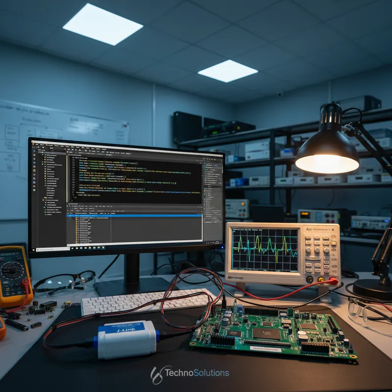
Pairing CoreSight with a professional probe is where the engineering leverage lives. Arm’s DSTREAM-ST and DSTREAM-PT trace probes with Corstone reference subsystems are the flagship trace solution for Cortex-M4 silicon with a full parallel trace port; for everyday SWD/SWO bring-up the Cortex-M4 also pairs with SEGGER J-Link and J-Trace probes, which is how most Indian firmware labs actually work. The professional IDE story runs through Arm Keil MDK for commercial Cortex-M development, and for teams straddling Cortex-A and Cortex-M in one product line it extends into Arm Development Studio for Cortex-A/R/Neoverse bring-up.
Cortex-M4 vs Cortex-M3 vs Cortex-M7: Which Is Right?
The Cortex-M4 sits between its simpler sibling the Cortex-M3 and its more powerful sibling the Cortex-M7 in the cortex m mcu lineup. The table below summarises the architectural differences that actually move the needle on a design review.
| Feature | Cortex-M3 | Cortex-M4 / M4F | Cortex-M7 |
|---|---|---|---|
| Architecture profile | Armv7-M | Armv7E-M (DSP-extended) | Armv7E-M (DSP-extended) |
| Instruction set | Thumb-2 | Thumb-2 | Thumb-2 |
| Pipeline | 3-stage | 3-stage | 6-stage, dual-issue, branch prediction |
| DSP extensions | No | Yes (MAC, SIMD, saturating) | Yes |
| FPU | None | Optional single-precision (M4F) | Optional single- or double-precision |
| MPU | Optional, 8 regions | Optional, 8 regions | Optional, 8 or 16 regions |
| Caches | None | None | Optional I-cache and D-cache |
| Tightly-coupled memory | No | No | Optional ITCM and DTCM |
| Typical clock ceiling | ~120 MHz | ~180 MHz | ~600 MHz |
| Typical CoreMark/MHz | ~3.3 | ~3.4 | ~5.0 |
| Bit-banding | Yes | Yes | No (optional in Armv7E-M; Arm did not implement it on Cortex-M7) |
| Unaligned access | Yes | Yes | Yes |
| Relative silicon cost | Lowest of the three | Mid | Highest |
The heuristic most Indian teams use: if the workload is control-dominated with no heavy signal processing, Cortex-M3 is the cheaper choice. If the workload has fixed-point DSP, light floating-point, motor control, audio, or sensor fusion, step up to Cortex-M4 or M4F; the DSP extensions and FPU pay for themselves. If the workload is heavy, vision preprocessing, multi-channel audio, 50+ kHz motor control, an LCD graphics stack, step up to Cortex-M7 for the dual-issue pipeline, caches, and tightly-coupled memories. We cover the three Cortex families at a higher level in the complete Arm Cortex processor family guide.
Silicon Vendors and Parts Available in India: Cortex-M4 Families
The Cortex-M4 is an Arm IP core, not a chip. Every silicon vendor builds its own memory hierarchy and peripheral set around the same core, and each of the families below is programmable with the same CMSIS-Pack ecosystem and the same Keil MDK or Arm Development Studio workflow.
- STMicroelectronics STM32F4: the most widely deployed Cortex-M4F family in Indian product design. STM32F407, F429, F446, F469. Up to 180 MHz, up to 2 MB flash, full FPU.
- NXP Kinetis K22 / K24 / K26: Cortex-M4F with FlexBus and FlexRAM, used in industrial sensor and metering applications.
- TI Tiva TM4C: TM4C123 (no FPU) and TM4C129 (Cortex-M4F with Ethernet MAC+PHY) for industrial connectivity and basic motor control.
- Microchip (formerly Atmel) SAM4: SAM4S, SAM4E, SAM4N, often seen in European-influenced product lines and academic reference designs.
- Silicon Labs EFM32 Giant Gecko: Cortex-M4F built on the energy-micro low-power architecture, for long-life battery and energy-harvesting applications.
- Nordic Semiconductor nRF52840: Cortex-M4F with integrated 2.4 GHz radio for Bluetooth LE, Thread, and Zigbee. On almost every Indian BLE product shipping in volume.
- Infineon XMC4000: XMC4500/4700/4800 Cortex-M4F parts oriented at industrial motor control with specialised PWM and delta-sigma demodulator peripherals.
Whichever family you pick, the core content in this article applies, NVIC, bit-banding, MPU, CMSIS headers all drop in unchanged.
Where the Cortex-M4 Sits in the Indian Product Landscape
The Cortex-M4 has taken real estate in several distinct Indian product categories.
BLDC and PMSM motor control. Ceiling fans, water pumps, electric two-wheeler drivetrains, HVAC compressors, and industrial conveyors are converging on Cortex-M4F running field-oriented control. DSP extensions run Clarke/Park, the FPU handles the PI controllers, and the NVIC delivers PWM-sync interrupts. 20 kHz SVPWM with a full FOC observer fits in a mid-range STM32F4 or XMC4000.
Low-power IoT sensor nodes. Indian agritech, cold-chain, and asset-tracking products lean on the nRF52840 and EFM32 Giant Gecko. Cortex-M4F runs sensor-fusion and BLE; SLEEPDEEP plus the silicon PMU delivers multi-year coin-cell operation.
Smart meters and energy monitoring. Indian utility meters run FFT harmonic analysis and fixed-point power computation, all inside the Cortex-M4 DSP budget.
Audio DSP and wearables. Voice-activated devices, fitness wearables, and hearing-assist products use the Cortex-M4F FPU and SIMD path for FIR, keyword spotting, and biquad EQ chains.
Industrial PLC and factory I/O. Mid-range Indian PLCs use the MPU to separate the scan engine, comms stack, and diagnostic task, giving a defensible safety story without a Cortex-R part.
Medical, infusion, ventilation, patient monitoring. Indian medical OEMs use Cortex-M4F where the MPU, NVIC determinism, and CMSIS-DSP libraries feed the functional-safety narrative.
In every category, the Cortex-M4 is capable enough to land the workload and restrained enough to hit the BOM and power targets Indian product teams have to respect.
Further Reading
Arm official references:
- Arm Cortex-M4 Processor, developer.arm.com, the official product page with links to the technical reference manual and architecture documentation.
- Armv7-M Architecture Reference Manual, developer.arm.com, the canonical specification covering both Armv7-M (Cortex-M3) and Armv7E-M (Cortex-M4, Cortex-M7).
Related GSAS engineering deep dives:
- Arm Cortex processor family, the complete list and comparison guide
- Arm Keil MDK-Professional for Indian Cortex-M commercial development
- Arm Development Studio for Cortex-A, Cortex-R, and Neoverse bring-up
- Arm MDK Middleware and CMSIS, the Indian industrial IoT firmware stack
- Arm DSTREAM-ST/PT and Corstone reference subsystems for Indian teams
- Arm Ethos-U microNPU on Cortex-M for edge AI in Indian products
- Arm, the partner page for tools, licensing, and support in India
GSAS Micro Systems is Arm’s authorized partner in India for Arm Development Tools, and our engineering team supports Cortex-M4 firmware programmes end-to-end, from silicon selection through Keil MDK licensing, CMSIS-DSP integration, J-Link and DSTREAM debug enablement, and production bring-up support. Indian customers across Bengaluru, Chennai, Hyderabad, Delhi NCR, Mumbai, and Pune lean on GSAS when they need a real engineering partner, not a paperwork channel, between the Arm ecosystem and their Cortex-M4 product. GSAS also designs and manufactures its own Cortex-M4 development board: the Genesis Cortex-M4 Bridge, an STM32F407 carrier board built in India and open for pre-order. If you are standing up a new Cortex-M4 platform this quarter, we would welcome the conversation.
Also appears in:
Interested in Arm tools?
Talk to our application engineers for personalized tool recommendations.
More from Arm
View all →
Meet the GSAS Team at electronica India 2026, Stall H3.I45
15 Sept · 3 min

Arm's Agentic AI Push: What Indian Embedded Teams Can Actually Use Today
13 Sept · 7 min
Arm User-Based Licensing in CI/CD: armlm, Proxy Activation and What Breaks
28 Jul · 11 min

Two Arm Keil MDK Webinars This Summer: DevOps and Edge AI for Indian Cortex-M Teams
17 Jun · 4 min

Emulating Processor Power for Thermal Testing: Why Constant Power
7 Oct · 7 min

CRPS and Rack Power Supply Testing: The Six Tests That Matter
7 Oct · 7 min