
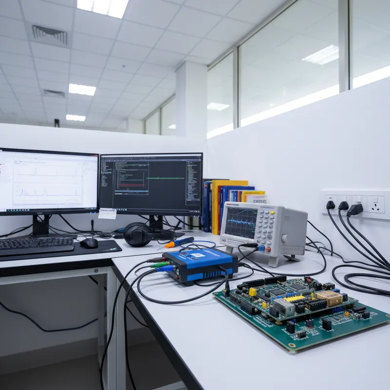
Why Estimation Is Not Enough
Battery life claims on product datasheets are typically derived from spreadsheet models: add up the datasheet current consumption of each component in each operating state, multiply by duty cycle, divide battery capacity by average current. The result is a number that looks precise but is often wrong, sometimes by a factor of 2x or more.
The problem is not the arithmetic. The problem is the inputs. Datasheet current specifications are typical values measured under ideal conditions on a characterization bench. Real-world devices have leakage paths through ESD protection structures, parasitic currents through pull-up resistors on unused GPIO pins, voltage regulator quiescent currents that vary with temperature, and firmware that does not behave exactly as the engineer intended.
A GPIO left in an intermediate state, a peripheral clock that was not gated, a DMA controller that stays active after a transfer completes, any of these can add microamps to the sleep current that the spreadsheet does not account for.
The only way to know a device’s actual battery life is to measure it. But measuring battery life directly, running a device until its battery dies, takes months for a product designed to last years. Engineers need a method that produces a reliable battery life prediction from hours of measurement, not months.
Measurement-Based Prediction
The Joulescope JS220’s combination of 0.5 nA resolution, 34-bit dynamic range, and 2 Msps continuous sampling makes measurement-based battery life prediction practical. The methodology has three phases: characterize, integrate, and project.
Phase 1: Characterize Every Operating State
Capture the device’s complete duty cycle, every transition from deep sleep through active operation and back, with the JS220. The 300 kHz bandwidth and zero-gap Enwavify autoranging ensure that no transient is missed, even sub-microsecond current spikes during voltage regulator switching or oscillator start-up.
Record multiple complete duty cycles (at least 20-30) to build a statistical sample. If the device’s duty cycle includes variable-length operations, a sensor read that takes different times depending on the measured value, or a radio transmission with variable payload sizes, capture enough cycles to represent the full distribution.
Phase 2: Energy Integration Per Cycle
Use the Joulescope UI’s energy integration feature or the Python API to compute the total charge (in coulombs) consumed during each complete duty cycle. A duty cycle is one complete period from the start of one sleep phase to the start of the next sleep phase, encompassing all active operations in between.
With 20-30 measured cycles, compute the mean charge per cycle and the standard deviation. The standard deviation captures the real variability in the device’s energy consumption, variable radio transmit times, retransmissions, sensor conditioning delays, that a spreadsheet model cannot predict.
Phase 3: Statistical Projection
Project battery life from the measured data:
Mean battery life = battery capacity / (mean charge per cycle x cycles per unit time)
Worst-case battery life = battery capacity / (P95 charge per cycle x cycles per unit time)
The worst-case estimate using the 95th percentile (P95) charge per cycle accounts for the tail of the distribution, the occasional cycles that consume more energy due to retransmissions, extended sensor conditioning, or environmental factors. This is the number that belongs on the product datasheet, because it represents the battery life that 95% of duty cycles will achieve or exceed.
For products with multiple operating modes, a wearable that measures heart rate continuously but transmits data only every 5 minutes, characterize each mode separately and combine the projections weighted by the duty cycle of each mode.
Building Confidence With Accelerated Validation
After computing the projected battery life, validate it with an accelerated test. Increase the duty cycle frequency, if the device normally wakes every 15 minutes, configure it to wake every 15 seconds. Run the accelerated test for 24-48 hours with the JS220 continuously logging energy consumption. Compare the measured cumulative energy against the projection.
If the accelerated test’s measured energy diverges from the projection by more than 5%, investigate. Temperature drift, battery voltage decay (which affects regulator efficiency and radio transmit power), and time-dependent leakage can all cause the actual consumption to differ from the initial characterization. The JS220’s unlimited capture duration and Python API enable automated monitoring of these extended validation runs.
Report Generation for Product Validation
A measurement-based battery life validation report includes:
- Test configuration: device firmware version, battery type and capacity, ambient temperature, duty cycle parameters
- Raw measurement data: per-cycle charge consumption with statistical summary (mean, standard deviation, min, max, P95)
- Projected battery life: mean and worst-case (P95) estimates with confidence intervals
- Accelerated validation results: measured vs. projected energy consumption over the validation period
- Instrument calibration: Joulescope JS220 serial number and calibration status (for the JS220+ variant, the ISO 17025:2017 NIST-traceable calibration certificate provides formal traceability)
This report format satisfies product validation requirements for consumer electronics, medical devices (IEC 62133 battery safety), and automotive components where battery life claims must be substantiated with measurement data.
Buy Joulescope in India from GSAS
GSAS provides Joulescope instruments, the JS220, JS220+ Precision variant, and Eval Kit, with INR invoicing, evaluation programs, and power profiling methodology workshops from offices in Bengaluru, Hyderabad, Chennai, Pune, Mumbai, and Delhi NCR.
Contact sales@gsasindia.com or call +91 80 6590 1783.
Also appears in:
Interested in Joulescope tools?
Talk to our application engineers for personalized tool recommendations.
More from Joulescope
View all →
Battery Discharge Profiling for Coin Cell Devices: From CR2032 to 10-Year Life
5 Apr · 7 min
BLE Power Profiling: Measuring Bluetooth Low Energy Current With Joulescope
5 Apr · 7 min
Energy Harvesting and Power Measurement: Designing Self-Powered IoT Devices
5 Apr · 7 min

IoT Battery Life Testing: A Practical Methodology for Indian Product Teams
5 Apr · 7 min

Emulating Processor Power for Thermal Testing: Why Constant Power
7 Oct · 7 min

CRPS and Rack Power Supply Testing: The Six Tests That Matter
7 Oct · 7 min


