PCIe Gen5 Eye Diagram Analysis: Ensuring 32 GT/s Link Compliance in Your Design
PCIe Gen5 doubles the data rate to 32 GT/s per lane, a 64 GHz Nyquist frequency that pushes the PCB interconnect into a regime where every via, every impedance discontinuity, and every inch of trace contributes measurable insertion loss. The channel loss budget at 16 GHz (the Nyquist frequency) is so tight that the difference between a compliant link and a failed one can be less than 2 dB. Eye diagram analysis is the definitive method for determining whether a PCIe Gen5 channel will operate reliably, and IBIS-AMI simulation in HyperLynx SI is how design teams predict eye performance before fabrication.
This is critical for server and networking teams building high-density compute platforms, and equally for automotive ADAS teams routing PCIe Gen5 links between SoCs and camera/radar data aggregators. Design teams in Bengaluru, Hyderabad, Pune, Chennai, Mumbai, and Delhi NCR are encountering PCIe Gen5 in current designs, and the simulation methodology described here applies to all of them.
Why PCIe Gen5 Channel Loss Is So Tight
PCIe Gen5 uses NRZ (PAM-2) signalling at 32 GT/s with a unit interval of 31.25 ps. The PCI-SIG specification defines the channel as the complete path from the transmitter package pin to the receiver package pin, including the PCB traces, vias, connectors, and any interposer or riser boards.
The specification allocates the total channel budget into three segments: the root complex (transmitter) package and breakout, the board-level channel, and the endpoint (receiver) package and breakout. For a typical add-in card topology (CEM connector), the board channel budget allows approximately 25–28 dB of insertion loss at 16 GHz. That sounds generous until you account for the real loss contributors.
Trace loss. FR-4 dielectric loss at 16 GHz is approximately 0.8–1.2 dB per inch, depending on the laminate grade. A 10-inch trace on standard FR-4 already consumes 8–12 dB. Low-loss laminates (Megtron 6, Tachyon, Panasonic R-5785N) reduce this to 0.4–0.6 dB per inch, but at higher material cost.
Via transitions. Each through-hole via adds 0.5–1.5 dB of insertion loss at 16 GHz, depending on stub length and whether back-drilling is used. A PCIe Gen5 channel with four via transitions (two at the add-in card, two at the root complex) can consume 2–6 dB on vias alone.
Connector loss. The CEM connector contributes 1–3 dB at 16 GHz. Board-to-board connectors for midplane/backplane topologies can be significantly worse.
Crosstalk. Near-end and far-end crosstalk from adjacent lanes degrade the effective signal-to-noise ratio, reducing the eye opening. In dense x16 slots with tight lane spacing, crosstalk can reduce the effective eye height by 10–20%.
When these losses are summed, the remaining margin is often single-digit dB, insufficient to absorb fabrication variation, temperature effects, and aging without simulation-based validation.
Equalization: CTLE and DFE
PCIe Gen5 relies on equalization at both the transmitter and receiver to recover the signal from a lossy channel.
Transmitter de-emphasis. The transmitter applies de-emphasis (reducing the amplitude of repeated bits relative to transition bits) to pre-compensate for the channel’s low-pass frequency response. PCIe Gen5 defines multiple transmitter presets with different de-emphasis levels. The optimal preset depends on the channel loss profile.
CTLE (Continuous Time Linear Equalizer). The receiver applies CTLE to boost the high-frequency content of the received signal, partially compensating for channel loss. CTLE gain is typically 6–12 dB at the Nyquist frequency for Gen5 channels. However, CTLE also amplifies crosstalk and noise, so excessive CTLE gain degrades the eye.
DFE (Decision Feedback Equalizer). After the CTLE, the receiver applies DFE to cancel inter-symbol interference from previous bits. DFE operates on the digital decision output and does not amplify noise, making it more effective than CTLE for channels with significant reflections. PCIe Gen5 receivers typically implement 1–4 DFE taps.
The interplay between transmitter preset, CTLE gain, and DFE tap values determines the final eye opening. Predicting this interplay requires IBIS-AMI simulation, it cannot be estimated from S-parameters alone.
Eye Diagram Analysis in HyperLynx SI
HyperLynx SI performs PCIe Gen5 eye diagram analysis using IBIS-AMI models provided by the silicon vendors. The workflow follows a systematic sequence.
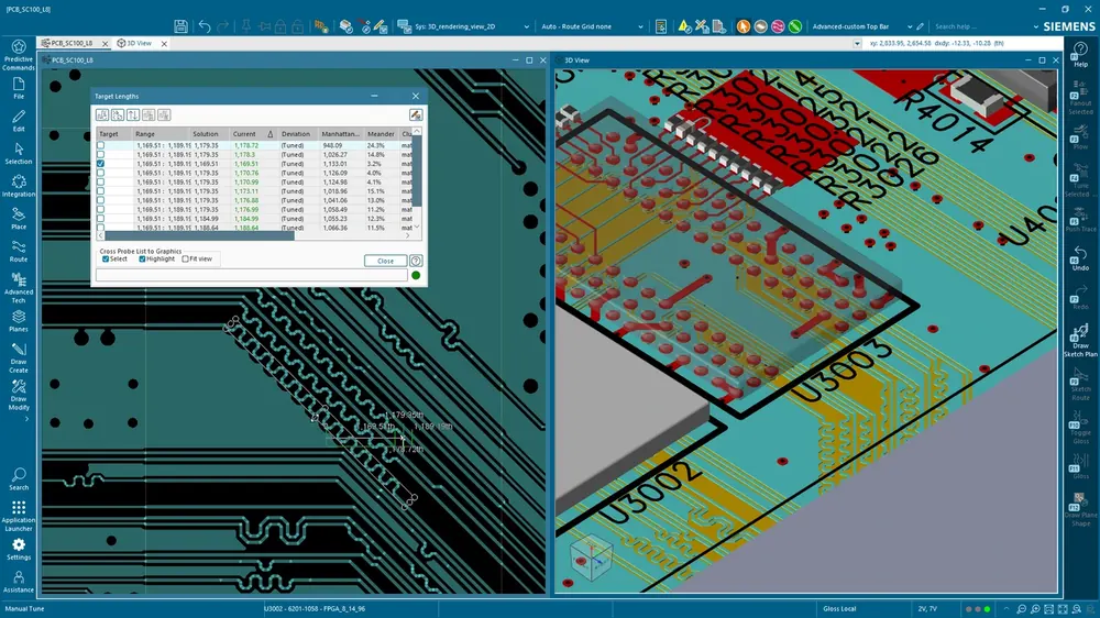
Channel extraction. From the post-layout design in Xpedition Enterprise or imported via ODB++, HyperLynx SI extracts the S-parameter model of the complete channel, traces, vias, connectors, and planes. This extraction captures the actual routed geometry, including impedance discontinuities that a simplified hand calculation would miss.
IBIS-AMI simulation. The extracted channel S-parameters are combined with the transmitter and receiver IBIS-AMI models. HyperLynx SI runs a statistical simulation that sweeps through all possible bit patterns and computes the probability distribution of the voltage at the receiver sampling point. The result is a statistical eye diagram that shows the eye opening at a given bit error rate (BER), typically 1e-12 for PCIe compliance.
Eye mask comparison. The simulated eye is overlaid on the PCIe Gen5 eye mask defined in the PCI-SIG CEM specification. The eye mask specifies the minimum eye height and width that the channel must achieve. HyperLynx SI reports the margin to the mask, how much additional loss or jitter the channel can tolerate before failing.
Transmitter preset sweep. HyperLynx SI can sweep across all PCIe Gen5 transmitter presets, identifying the optimal preset for the specific channel. This analysis reveals whether the channel requires a specific preset to pass compliance, information that is critical for BIOS/firmware configuration.
S-Parameter Analysis and Via Optimization
Before the full IBIS-AMI eye simulation, S-parameter analysis in HyperLynx SI helps the designer understand the channel’s intrinsic quality.
Insertion loss (IL). The |S21| parameter shows the channel attenuation versus frequency. For PCIe Gen5, the insertion loss at 16 GHz must stay within the specification budget. If the raw insertion loss exceeds the budget, the designer must shorten traces, use lower-loss laminates, or back-drill vias.
Return loss (RL). The |S11| parameter shows impedance matching quality. Excessive return loss (poor matching) at specific frequencies indicates impedance discontinuities, typically at via transitions or connector interfaces, that create reflections.
Crosstalk (NEXT and FEXT). The coupling S-parameters (S31, S41, etc.) quantify crosstalk between adjacent lanes. For PCIe Gen5 x16 configurations, the aggregate crosstalk from 15 adjacent lanes can significantly impact the victim lane’s eye opening.
Via optimization is often the highest-impact improvement for PCIe Gen5 channels. HyperLynx SI S-parameter analysis shows the via’s resonant frequency and insertion loss. Back-drilling to remove the stub shifts the resonance above the Nyquist frequency, recovering 1–3 dB of insertion loss, often the difference between a passing and failing eye.
Automotive PCIe Gen5: ADAS and Camera Data
Automotive ADAS platforms are increasingly adopting PCIe Gen5 for aggregating data from cameras, radar, and lidar sensors. The SoC connects to a PCIe switch, which fans out to multiple sensor interface modules. These designs face unique challenges.
Extended temperature range. Automotive operating temperatures (-40 to +125 C) cause impedance variations in the PCB traces and connector contacts. SI simulation must account for worst-case temperature conditions, not just room temperature.
Vibration and mechanical stress. Automotive connectors are subject to vibration, which can degrade contact resistance over the vehicle’s lifetime. The SI margin must include a budget for connector degradation.
EMI constraints. Automotive EMC requirements (CISPR 25, ISO 11452) are stringent. PCIe Gen5 at 32 GT/s generates significant high-frequency energy that must be contained through controlled impedance routing, reference plane integrity, and proper connector shielding.
HyperLynx SI combined with HyperLynx PI for power delivery analysis provides the comprehensive simulation coverage that automotive ADAS designs require.
Compliance to PCI-SIG CEM Specification
PCIe Gen5 compliance testing follows the PCI-SIG CEM (Card Electromechanical) specification, which defines the channel requirements in terms of insertion loss, return loss, crosstalk, and eye diagram parameters. Designs that fail compliance testing at the PCI-SIG workshop face costly redesigns and schedule delays.
HyperLynx SI’s pre-silicon compliance checking allows the design team to verify against the CEM specification before building hardware. The simulation reports map directly to the compliance test measurements, giving the team confidence that the design will pass when it reaches the test lab.
Designing a PCIe Gen5 platform? GSAS Micro Systems supports server, networking, and automotive teams across Bengaluru, Hyderabad, Chennai, Pune, Mumbai, and Delhi NCR with HyperLynx SI licensing, PCIe Gen5 channel simulation training, and technical assistance from engineers who understand high-speed serial link design.
Also appears in:
Interested in Siemens EDA tools?
Talk to our application engineers for personalized tool recommendations.
More from Siemens EDA
View all →
India's EDA Moment: Why Design Tool Demand Is Growing, and the Engineering Careers It Creates
21 Sept · 9 min

AI and Complexity Are Redrawing EDA: Siemens on the Trillion-Transistor Era
13 Sept · 6 min

Calibre Vision AI: Bringing Order to DRC Debug at Advanced Nodes
24 Aug · 4 min

Siemens EDA EBS Expert Series: 6 Free PCB Design Webinars (Jul-Aug 2026)
20 Jul · 8 min

Emulating Processor Power for Thermal Testing: Why Constant Power
7 Oct · 7 min

CRPS and Rack Power Supply Testing: The Six Tests That Matter
7 Oct · 7 min