
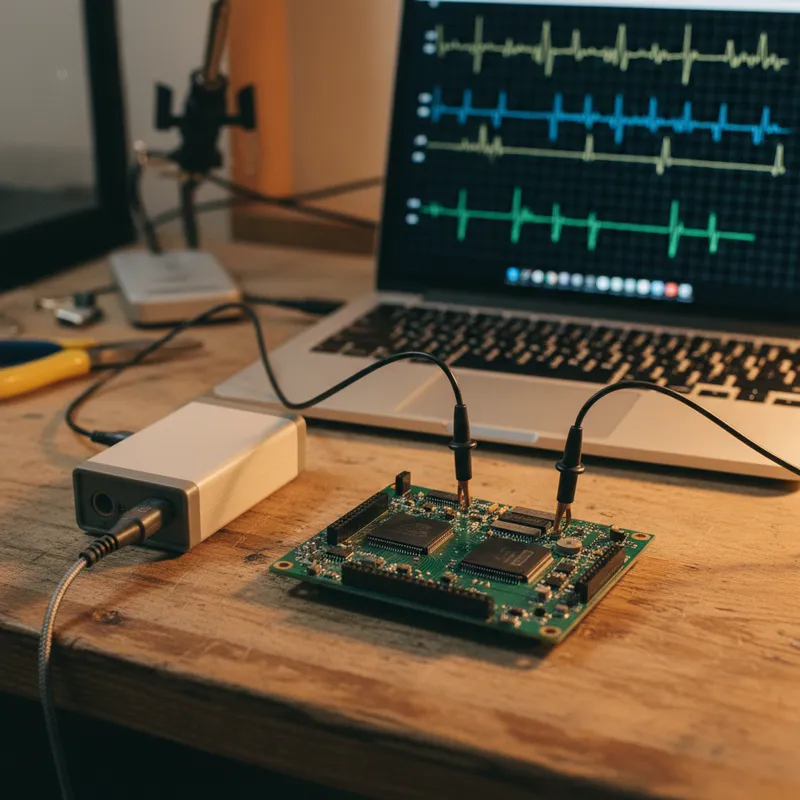
6 Simultaneous Probe Points: Multi-Point Measurement with Sensepeek PCBite
Most oscilloscope measurements start with a single probe on a single node. But many real-world debugging scenarios demand simultaneous visibility into multiple signals, power sequencing across three voltage rails, clock-to-data timing on a parallel bus, or correlating a control signal with its downstream effect. The Sensepeek PCBite platform supports six or more probe points on a single board, all positioned independently and held in place magnetically.
This post covers practical multi-point measurement setups, the hardware you need, and the techniques that make six-probe debugging productive rather than chaotic.
The Hardware Setup
A standard PCBite kit includes two oscilloscope probes (SQ200 or SQ500) and four SQ10 general-purpose probes, for a total of six probe points out of the box. The DIN A4 stainless steel base plate (297 x 210 mm) has enough surface area for six or more articulating arms without mechanical interference, though probe density depends on board size and component spacing.
The typical six-probe configuration:
- Channels 1-2: SQ200 or SQ500 probes connected to oscilloscope analog channels for waveform capture
- Channels 3-6: SQ10 probes connected to a logic analyzer, multimeter, or additional oscilloscope channels for DC measurements and digital signal decoding
Each probe mounts on its own articulating arm with a magnetic base. You position each arm independently, angle, height, and lateral position, then the magnet locks it to the base plate. The spring-loaded 0.5 mm needle tip on each probe maintains consistent contact pressure on the target pad.
Application: Power Supply Sequencing
Power sequencing is one of the most common multi-point measurement scenarios in embedded system bring-up. A typical SoC or FPGA board has three to five voltage rails that must power up in a defined order with specific timing constraints. Measuring one rail at a time tells you nothing about inter-rail timing.
With six PCBite probes, a power sequencing debug session looks like this:
- Position two SQ200 probes on the two most critical rails, typically the core supply and the I/O supply
- Position four SQ10 probes on the remaining rails, the power-good signals, and the enable lines
- Connect the SQ200 probes to a two-channel oscilloscope and the SQ10 probes to a logic analyzer or additional scope channels
- Trigger on the enable signal and capture the full sequence in a single acquisition
The probes stay in position across power cycles. You can adjust regulator feedback resistors, modify sequencing firmware, or swap load resistors without re-establishing probe contact. For hardware teams in Bengaluru and Pune doing FPGA board bring-up, this saves significant time during the iterative sequencing debug process.
Application: Clock-Data Timing Analysis
Serial interfaces like SPI, I2C, and parallel buses require correlation between clock and data signals. With a single probe, you measure clock and data sequentially and hope the timing relationship has not changed between measurements. With multi-point PCBite probing, you capture clock, data, chip select, and status signals simultaneously.
A six-point SPI debug setup:
- SQ200 or SQ500 on SCLK (to see edge quality at the bandwidth you need)
- SQ200 or SQ500 on MOSI or MISO (data line under investigation)
- SQ10 on chip select (CS)
- SQ10 on a second data line or interrupt output
- SQ10 on VCC (to correlate power dips with bus activity)
- SQ10 on a GPIO debug pin (firmware timing marker)
This level of instrumentation is what makes intermittent bus errors diagnosable. A glitch that only occurs when CS transitions during a power supply droop will never be caught with a single-probe measurement.
Application: Analog-Digital Correlation
Mixed-signal systems, motor controllers, sensor interfaces, power converters with digital feedback loops, often require correlating analog waveforms with digital control signals. Place the SQ200 or SQ500 probes on the analog nodes (current sense resistor, voltage feedback divider, PWM output) and the SQ10 probes on the digital control signals (enable, fault, direction, communication bus). The simultaneous capture reveals cause-and-effect relationships that are invisible in sequential measurements.
For teams in Hyderabad and Chennai developing motor drives or industrial automation controllers, this analog-digital correlation capability is directly relevant to tuning PID loops, characterizing startup transients, and diagnosing fault conditions.
Practical Tips for Multi-Probe Setups
Cable routing matters. Six probe cables competing for space create mutual inductance coupling and mechanical pull on the articulating arms. Use the color-coded cable holders included with the SQ-series probes to route cables away from each other and away from the board under test. Route high-bandwidth cables (SQ200/SQ500) on opposite sides of the board from SQ10 cables where possible.
Ground strategy. Each probe needs a ground reference. On a board with exposed ground planes or numerous ground vias, each probe can use its own ground spring connected to the nearest ground pad. Avoid daisy-chaining ground connections between probes, each probe’s ground path should be short and independent.
Label your channels. With six probes active, it is easy to lose track of which probe connects to which oscilloscope or logic analyzer channel. The SQ-series color-coded cable holders help, but annotating your oscilloscope channel labels (most modern scopes support this) removes ambiguity.
Start with fewer probes, then add. Position and verify your two most critical measurement points first. Confirm the oscilloscope is triggering correctly and the signals look reasonable. Then add the remaining probes one at a time. This avoids the frustration of debugging a six-probe setup where one misplaced needle is corrupting your trigger.
Expanding Beyond Six Points
The PCBite base plate can physically accommodate more than six probes. If your oscilloscope and logic analyzer have additional channels, you can add individual SQ10, SQ200, or SQ500 probes to the setup. The magnetic mount is the same across all SQ-series probes, so every addition is mechanically identical.
Why Buy from GSAS
GSAS is an authorized engineering partner in India. Our application engineers in Bengaluru, Hyderabad, Chennai, Pune, Mumbai, and Delhi NCR help teams configure multi-point measurement setups and select the right combination of SQ10, SQ200, SQ500, and SQG probes for their instrumentation needs. We provide INR invoicing, evaluation kits, and guidance on integrating PCBite probes with your existing oscilloscopes and logic analyzers. Contact GSAS for pricing and multi-probe configuration advice.
Also appears in:
Interested in Sensepeek tools?
Talk to our application engineers for personalized tool recommendations.
More from Sensepeek
View all →
Shrinking Boards, Growing Problems: Why Hands-Free Probing Is Essential as Component Density Rises
7 Apr · 4 min

Getting Started with Sensepeek PCBite: Unboxing to First Measurement
7 Apr · 5 min
High-Speed Interface Validation with Sensepeek SQG Probes: USB, HDMI, and SATA
7 Apr · 5 min
Sensepeek PCBite Oscilloscope Compatibility: PicoScope, Keysight, Tektronix, R&S, and GW Instek
7 Apr · 4 min

Emulating Processor Power for Thermal Testing: Why Constant Power
7 Oct · 7 min

CRPS and Rack Power Supply Testing: The Six Tests That Matter
7 Oct · 7 min


