
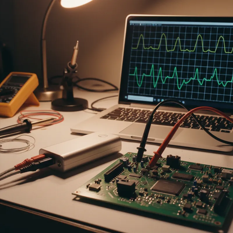
High-Speed Interface Validation with Sensepeek SQG Probes: USB, HDMI, and SATA
Validating signal integrity on multi-gigabit serial interfaces, USB 3.x, HDMI, SATA, PCIe, demands probes with bandwidth measured in gigahertz and capacitive loading measured in sub-picofarad fractions. Standard oscilloscope probes, even the 500 MHz SQ500, cannot capture the frequency content in a 5 Gbps USB 3.0 data eye. This is the domain of Sensepeek’s SQG-series high-frequency probes: passive 10:1 probes spanning 1.5 GHz to 6 GHz, with SMA output for 50-ohm instruments, all compatible with the PCBite hands-free platform.
This post maps SQG probe capabilities to specific high-speed interfaces and covers the practical considerations for GHz-class probing in a desktop lab environment.
Matching Probe Bandwidth to Interface Data Rate
The fundamental rule for oscilloscope probing applies at GHz frequencies just as it does at lower speeds: probe bandwidth should be at least 2x the signal’s fundamental frequency, and ideally 3-5x for accurate edge-rate characterization. For serial interfaces, the “fundamental frequency” is half the data rate (since data transitions occur at most once per bit period in NRZ signaling).
| Interface | Data Rate | Min Probe BW | Recommended SQG |
|---|---|---|---|
| USB 2.0 High Speed | 480 Mbps | 480 MHz | SQG15 (1.5 GHz) |
| Gigabit Ethernet | 1.25 Gbps | 1.25 GHz | SQG15 (1.5 GHz) |
| SATA Gen 1 | 1.5 Gbps | 1.5 GHz | SQG15 (1.5 GHz) |
| SATA Gen 2 | 3 Gbps | 3 GHz | SQG30 (3 GHz) |
| USB 3.0 | 5 Gbps | 5 GHz | SQG60 (6 GHz) |
| USB 3.1 Gen 2 | 10 Gbps | 10 GHz | Beyond SQG range |
| HDMI 1.4 | 3.4 Gbps | 3.4 GHz | SQG60 (6 GHz) |
| HDMI 2.0 | 6 Gbps | 6 GHz | SQG60 (6 GHz) |
| PCIe Gen 2 | 5 GT/s | 2.5 GHz | SQG30 (3 GHz) |
| PCIe Gen 3 | 8 GT/s | 4 GHz | SQG60 (6 GHz) |
The SQG probes are passive 10:1 designs with 500-ohm probe tip impedance. Unlike the SQ-series probes that connect to 1 M-ohm oscilloscope inputs, SQG probes output via SMA connector to 50-ohm instruments, high-bandwidth oscilloscopes, sampling oscilloscopes, spectrum analyzers, or network analyzers.
USB Signal Integrity: A Practical Example
USB is among the most common high-speed interfaces on embedded boards. USB 2.0 runs at 480 Mbps, USB 3.0 at 5 Gbps, a ten-fold jump that requires a completely different probing strategy.
USB 2.0 with SQG15
For USB 2.0 eye diagram measurements, the SQG15 at 1.5 GHz provides comfortable margin over the 480 Mbps data rate. Position the SQG15 probe on the D+ or D- line at the connector or near the PHY IC. Use the AC-coupled variant (SQG15-AC) if you only need signal quality metrics, eye height, eye width, jitter. Use the DC-coupled variant (SQG15-DC) if you need to verify DC bias levels or see the idle bus state.
The SQG15’s 1.36 pF tip capacitance and sub-190 ps rise time preserve USB 2.0 edge fidelity without meaningfully loading the 45-ohm differential pair. Ground via the 2.3 mm dual-needle ground, placing the ground needles on the USB connector shield or the nearest ground pad.
USB 3.0 with SQG60
USB 3.0’s 5 Gbps data rate requires probing bandwidth approaching 5 GHz for clean eye diagram capture. The SQG60 at 6 GHz is the appropriate probe. The ultra-low tip capacitance minimizes reflections that would distort the eye opening on a tightly controlled 85-ohm differential transmission line.
Position the probe at the connector end (for compliance-style measurement) or at the PHY receiver input (for link-quality diagnosis). Use AC coupling (SQG60-AC) for eye diagram analysis, blocking the DC common-mode voltage and focusing on signal transitions.
HDMI Validation
HDMI 1.4 transmits up to 3.4 Gbps per TMDS lane. HDMI 2.0 pushes this to 6 Gbps per lane. The SQG60 covers both standards with 6 GHz bandwidth.
The challenge with HDMI probing is physical access. HDMI connector pins are closely spaced, and the differential pairs are typically routed as controlled-impedance traces on internal layers. Probing requires either a test coupon with exposed pads or a board design that includes dedicated high-speed test points near the HDMI PHY.
The SQG60’s 0.5 mm spring-loaded needle can reach pads that standard SMA-terminated probe tips cannot, a practical advantage for design teams in Bengaluru and Hyderabad doing pre-compliance checks on consumer electronics boards without dedicated HDMI test fixtures.
SATA Interface Debugging
SATA Gen 1 (1.5 Gbps) and Gen 2 (3 Gbps) are common in industrial and storage-oriented embedded systems. The SQG15 covers SATA Gen 1, and the SQG30 covers Gen 2 with its 3 GHz bandwidth and 0.35 pF tip capacitance, the lowest in the SQG family.
SATA link integrity issues often manifest as intermittent read errors or speed fallback (Gen 2 falling back to Gen 1). Probing the TX differential pair at the PHY output with an SQG probe and capturing the eye diagram reveals whether the root cause is signal quality (jitter, amplitude, rise time) or a system-level issue (cable quality, connector contact).
Ground Strategy at GHz Frequencies
Ground path quality dominates measurement accuracy at GHz frequencies. The SQG probes provide two ground options:
- 2.3 mm dual-needle ground: Two spring-loaded ground needles spaced 2.3 mm apart. Designed for closely spaced ground pads or RF connector shields. Provides the shortest ground loop and lowest inductance.
- 6.5 mm single-ground spring: A single spring contact for wider ground pad spacing. Slightly longer ground path, but accommodates boards where ground pads are not immediately adjacent to the signal pad.
Always use the shortest available ground connection. At 3 GHz, even a 5 mm increase in ground path length adds measurable inductance that produces overshoot and ringing artifacts in the waveform. For teams in Chennai and Pune doing production-level signal integrity checks, standardizing on the dual-needle ground configuration ensures consistent measurement quality across operators.
Instrument Requirements
SQG probes output via SMA to 50-ohm instruments. Your oscilloscope must have 50-ohm input capability and bandwidth matching or exceeding the probe. Pairing an SQG60 (6 GHz) with a 1 GHz oscilloscope limits system bandwidth to 1 GHz, the probe’s capability is wasted. For USB 3.0 and HDMI 2.0 work, a 4 GHz or higher oscilloscope is the practical minimum.
Sampling oscilloscopes offer an alternative path for teams that need eye diagram analysis without the cost of a real-time GHz oscilloscope. The SQG probes’ SMA output connects directly to sampling oscilloscope channels for repetitive signal analysis.
Why Buy from GSAS
GSAS is an authorized engineering partner in India, providing the full SQG probe family alongside SQ-series kits for complete probing coverage from 10 MHz to 6 GHz. Our application engineers in Bengaluru, Hyderabad, Chennai, Pune, Mumbai, and Delhi NCR help teams match SQG probe bandwidth and coupling to their specific interface validation requirements. We provide INR invoicing, evaluation units, and integration guidance with high-bandwidth oscilloscopes. Contact GSAS for pricing and signal integrity probing consultation.
Also appears in:
Interested in Sensepeek tools?
Talk to our application engineers for personalized tool recommendations.
More from Sensepeek
View all →
Shrinking Boards, Growing Problems: Why Hands-Free Probing Is Essential as Component Density Rises
7 Apr · 4 min

Getting Started with Sensepeek PCBite: Unboxing to First Measurement
7 Apr · 5 min
6 Simultaneous Probe Points: Multi-Point Measurement with Sensepeek PCBite
7 Apr · 4 min
Sensepeek PCBite Oscilloscope Compatibility: PicoScope, Keysight, Tektronix, R&S, and GW Instek
7 Apr · 4 min

Emulating Processor Power for Thermal Testing: Why Constant Power
7 Oct · 7 min

CRPS and Rack Power Supply Testing: The Six Tests That Matter
7 Oct · 7 min


