
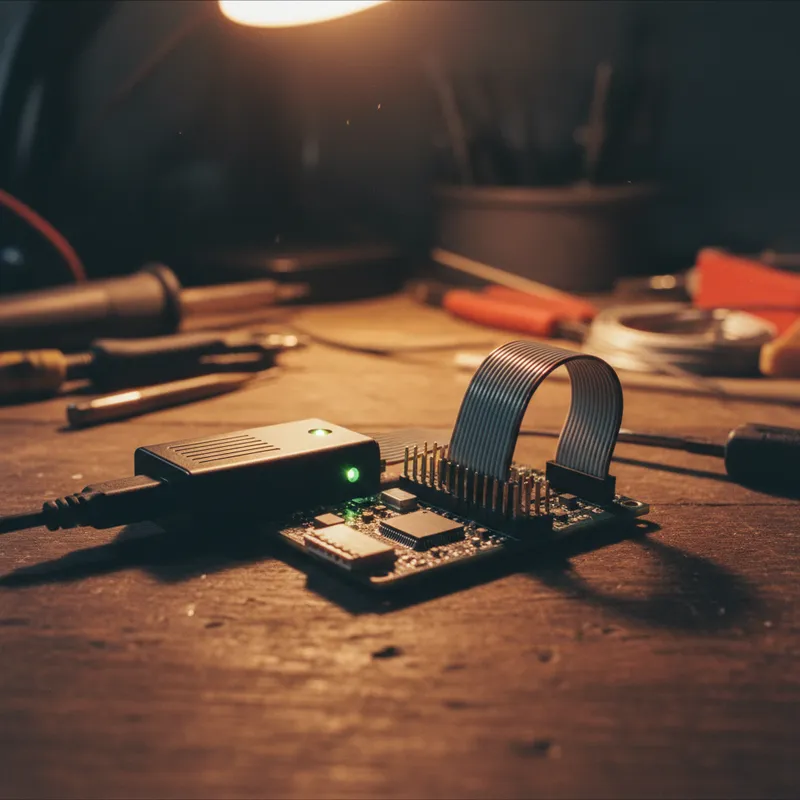
Probing 0402 Pads and QFN Pins: Fine-Pitch SMD Debugging with Sensepeek PCBite
Modern PCB designs have a probing problem. As components shrink from 0805 to 0402 (and beyond), as QFP packages give way to QFN and BGA, and as board densities push traces and pads closer together, the traditional oscilloscope probe tip becomes too large and too clumsy to make reliable contact. A standard probe tip designed for through-hole test points is physically incapable of landing cleanly on a 0.5 mm QFN pad without shorting to the adjacent pin.
The Sensepeek PCBite system was designed around this reality. Every probe in the SQ and SQG families uses a 0.5 mm diameter spring-loaded test needle, thin enough to contact individual pads on fine-pitch components, with consistent spring pressure that maintains contact without manual force.
The Fine-Pitch Access Problem
Consider a QFN-48 package with 0.5 mm pitch, common on microcontrollers, power management ICs, and RF transceivers used across Indian electronics design centers. The exposed pad width is approximately 0.25 mm, with 0.25 mm gap to the next pad. A conventional probe tip with a 1-2 mm contact surface cannot distinguish between adjacent pads at this pitch. Even a sharpened probe tip requires a steady hand and constant pressure to maintain contact on a single pad.
The situation is worse with BGA packages. Unless the board includes dedicated breakout pads routed from the BGA ball grid to accessible locations, there is no exposed metal to probe at all. Design teams in Bengaluru and Hyderabad working with high-density BGA processors routinely face this challenge: the signal you need to measure exists only on a 0.4 mm breakout via pad buried between power planes.
0402 passive components (1.0 x 0.5 mm) present similar constraints. The solder pad is tiny, and the component body offers no grab point for clip-on leads. Probing a decoupling capacitor or a series termination resistor on a dense board requires a probe tip that can reach the pad without disturbing adjacent components.
How PCBite Solves It
The Sensepeek approach combines three design elements:
1. Spring-Loaded 0.5 mm Needle Tips
Every SQ and SQG probe uses an exchangeable spring-loaded test needle with a 0.5 mm tip diameter. The spring mechanism provides two benefits: it maintains consistent contact pressure regardless of how precisely you position the probe height, and it absorbs vibration and thermal expansion without losing contact. The needle can reach individual pads on 0.5 mm pitch QFN packages, 0402 component terminals, and BGA breakout vias.
The needles are consumables, they wear over time, especially when probing hard solder alloys. Sensepeek includes replacement needles with every kit and sells them separately. Swapping a needle takes seconds.
2. Magnetic Articulating Arms
Each probe mounts in an articulating arm with a powerful magnetic base that locks to the stainless steel base plate. You position the arm so the needle tip hovers over the target pad, lower it until the spring engages, and the magnet holds everything in place. The articulating joint provides angular adjustment so you can approach a pad from the optimal angle, even on crowded boards where vertical access is blocked by tall components.
This is where the hands-free advantage directly enables fine-pitch work. Holding a probe tip on a 0.25 mm pad by hand for more than a few seconds is impractical, your hand moves, the probe slips, and you lose the measurement. The magnetic mount eliminates this problem entirely.
3. Board-Level Magnetic Fixturing
The four CNC-machined aluminum PCB holders grip the board under test magnetically to the base plate. The board does not shift when you position probes, and it does not flex when needle pressure is applied. This mechanical stability is essential for fine-pitch probing, if the board moves even 0.2 mm during probe placement, you land on the wrong pad.
Practical Workflow for Fine-Pitch Probing
A typical fine-pitch debugging session with PCBite looks like this:
- Mount the board on the magnetic PCB holders. Position the target component area roughly centered on the base plate.
- Identify target pads using the schematic and board layout. For BGA, confirm that breakout pads exist and note their locations.
- Position the first probe by adjusting the articulating arm over the target pad.
Use magnification (a USB microscope or loupe) to verify needle placement on fine-pitch pads below 0.5 mm. 4. Set the ground connection using the probe’s ground spring or clip, connecting to the nearest ground pad or via. 5. Add additional probes as needed. The PCBite base plate supports multiple probes simultaneously, each independently positioned. Multi-channel measurements on adjacent QFN pins or parallel bus lines become straightforward. 6. Acquire and analyze waveforms.
Because the probes maintain position, you can iterate on oscilloscope settings, firmware changes, or power supply adjustments without re-establishing contact.
For teams in Chennai and Pune doing production bring-up or failure analysis on fine-pitch assemblies, this workflow eliminates the repeated “probe, slip, re-probe” cycle that wastes time and risks pad damage.
Probe Selection for Fine-Pitch Work
All PCBite probes use the same 0.5 mm needle, so the fine-pitch access capability is consistent across the lineup:
- SQ10 for DC measurements and logic analyzer connections on fine-pitch digital buses
- SQ200 and SQ500 for oscilloscope measurements on fine-pitch analog and mixed-signal nodes
- SQG15, SQG30, and SQG60 for high-frequency signal integrity measurements on fine-pitch RF and high-speed digital pads
The choice depends on bandwidth requirements, not on physical access, the needle tip is the same across all models.
Why Buy from GSAS
GSAS is an authorized engineering partner in India. Our application engineers in Bengaluru, Hyderabad, Chennai, Pune, and Mumbai provide hands-on guidance for fine-pitch probing setups, including probe and kit selection based on your component packages and measurement bandwidth. We offer INR invoicing, evaluation units for bench trials, and replacement needle supplies. Contact GSAS for pricing and to arrange a demonstration with your specific board.
Also appears in:
Interested in Sensepeek tools?
Talk to our application engineers for personalized tool recommendations.
More from Sensepeek
View all →
Shrinking Boards, Growing Problems: Why Hands-Free Probing Is Essential as Component Density Rises
7 Apr · 4 min

Getting Started with Sensepeek PCBite: Unboxing to First Measurement
7 Apr · 5 min
High-Speed Interface Validation with Sensepeek SQG Probes: USB, HDMI, and SATA
7 Apr · 5 min
6 Simultaneous Probe Points: Multi-Point Measurement with Sensepeek PCBite
7 Apr · 4 min

Emulating Processor Power for Thermal Testing: Why Constant Power
7 Oct · 7 min

CRPS and Rack Power Supply Testing: The Six Tests That Matter
7 Oct · 7 min


