
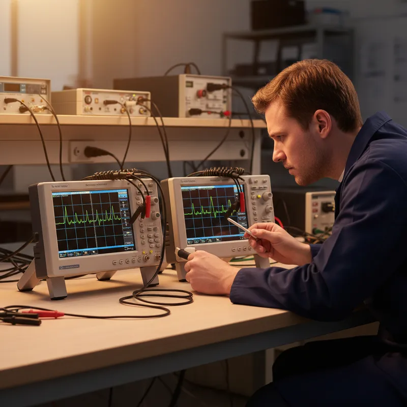
PCBite Hands-Free vs Traditional Clip-On Probes: A Practical Comparison
Every oscilloscope ships with a pair of passive probes, typically a set of 10:1 probes with hook tips, ground clips, and spring-loaded grabber accessories. These probes work. Engineers have used them for decades to debug everything from power supplies to serial buses. So when a system like Sensepeek’s PCBite offers a fundamentally different probing approach, magnetic base, articulating arms, spring-loaded needles, the fair question is: what does it actually improve?
This post compares the two approaches across five dimensions that matter in daily embedded hardware debugging.
1. Probe Tip Access: Hook Tips vs Spring Needles
Traditional probe tips are designed for through-hole test points and large SMD pads. The standard hook tip is roughly 1-2 mm wide at the contact point, and the spring-loaded grabber accessory is wider still. On a legacy board with 0805 components and generous test point pads, these tips work fine.
On modern boards with 0402 passives, 0.5 mm pitch QFN packages, and BGA breakout vias, traditional probe tips are physically too large. You end up removing the hook tip, filing the inner probe to a sharper point, and hand-holding it against a microscopic pad, a fragile setup that breaks contact at the slightest movement.
The PCBite SQ-series and SQG-series probes use a 0.5 mm spring-loaded exchangeable needle. The needle diameter matches the pad sizes of modern fine-pitch components. No modification required, no steady-hand heroics, the needle lands on the pad and the spring maintains contact.
2. Hands-Free Stability: Held vs Mounted
With a traditional probe, one hand holds the probe and the other adjusts the oscilloscope or types commands. This works for a quick check, but it breaks down in three common scenarios:
- Long debug sessions where you need to monitor a signal for minutes while changing firmware or adjusting power supply settings. Holding a probe tip on a pad for ten minutes is physically taxing and unreliable.
- Multi-channel measurements where you need three or four probes active simultaneously. With traditional probes, this requires either additional hands (a colleague, or probe holders cobbled from alligator clips and lab stands) or accepting that some probes will slip.
- Reproducible setups where you need the same measurement configuration across multiple boards or test sessions. Re-establishing traditional probe contact on the exact same pads produces variation in contact quality each time.
The PCBite magnetic mounting system addresses all three. Each probe locks into an articulating arm on the stainless steel base plate. Once positioned, it stays. You can set up four probes on a power sequencing measurement, walk away, come back the next day, and the probes are exactly where you left them.
For production-line bring-up in Bengaluru or Pune: where the same test setup must be repeated across dozens of boards, this repeatability eliminates a meaningful source of measurement variation.
3. Ground Connection Quality
Traditional oscilloscope probes use a ground clip lead, a wire 10-15 cm long with an alligator clip. At frequencies above a few tens of megahertz, this ground lead acts as an antenna, picking up noise and adding inductance that distorts the measurement. The standard advice is to remove the ground clip and use the probe’s ground barrel or a short ground spring, but many engineers skip this step because it is inconvenient.
PCBite probes include short ground options by design. The SQ-series probes offer ground springs and clips optimized for short ground paths. The SQG high-frequency probes provide a 2.3 mm dual-needle ground and a 6.5 mm single ground spring, both dramatically shorter than a dangling alligator clip lead.
For signal integrity work in Hyderabad and Chennai where ground loop inductance directly corrupts the measurement, the built-in short ground options are not an accessory, they are the default.
4. Multi-Point Measurement Scalability
A typical embedded debug scenario might require monitoring VCC, a clock output, a data line, and a reset signal simultaneously. With traditional probes, four-channel measurement means four probes, four ground clips, and a tangle of cables competing for space on the board. Positioning the fourth probe without displacing the first three is a practiced skill.
The PCBite system scales more cleanly. Each probe has its own magnetic base on the plate, positioned independently. Color-coded cable holders route the probe cables without tangling. Adding the fifth or sixth measurement point is the same mechanical operation as adding the first, position the arm, lower the needle, let the magnet lock.
The PCBite kits come with four SQ10 probes plus two oscilloscope probes specifically because multi-point measurement is the expected workflow, not an exception.
For teams in Mumbai and Pune doing board-level failure analysis or power integrity profiling, the ability to instrument six or more points simultaneously on a single board without mechanical conflict is a significant workflow improvement.
5. Exchangeable Tips and Long-Term Cost
Traditional probe tips wear and break. Replacement tips from oscilloscope manufacturers tend to be proprietary and moderately expensive. Many engineers use probes with damaged tips far longer than they should because replacements are not readily available.
PCBite probe needles are designed as consumables. Replacement needle packs are inexpensive and available from stock. Swapping a needle takes seconds, no tools, no calibration. This makes it practical to replace needles proactively, maintaining consistent contact quality over time. Given the spring-loaded design, needle wear is gradual and predictable rather than catastrophic.
Which Approach Is Right?
Traditional probes are not going away. They are included with every oscilloscope, they work without any setup, and they are fine for quick one-point measurements on accessible test points.
The PCBite system earns its place when your work involves fine-pitch components, multi-channel measurements, repeatable test setups, or long debug sessions. It does not replace your oscilloscope’s bundled probes, it supplements them with a purpose-built platform for the measurement challenges that bundled probes handle poorly.
The recommended starting point is a PCBite Kit with SQ200 probes for general embedded work, or a kit with SQ500 probes for high-speed digital debugging. Add SQG-series probes individually when GHz-class signal integrity measurements enter your workflow.
Why Buy from GSAS
GSAS is an authorized engineering partner in India. Our application engineers in Bengaluru, Hyderabad, Chennai, Pune, and Mumbai help teams evaluate the PCBite system against their current probing workflow and select the right kit and probe combination. We provide INR invoicing, local inventory, evaluation units, and ongoing support including replacement needle supplies. Contact GSAS for pricing and to discuss your measurement setup.
Also appears in:
Interested in Sensepeek tools?
Talk to our application engineers for personalized tool recommendations.
More from Sensepeek
View all →
Shrinking Boards, Growing Problems: Why Hands-Free Probing Is Essential as Component Density Rises
7 Apr · 4 min

Getting Started with Sensepeek PCBite: Unboxing to First Measurement
7 Apr · 5 min
High-Speed Interface Validation with Sensepeek SQG Probes: USB, HDMI, and SATA
7 Apr · 5 min
6 Simultaneous Probe Points: Multi-Point Measurement with Sensepeek PCBite
7 Apr · 4 min

Emulating Processor Power for Thermal Testing: Why Constant Power
7 Oct · 7 min

CRPS and Rack Power Supply Testing: The Six Tests That Matter
7 Oct · 7 min


