In short
SerDes camera links carry uncompressed automotive video over one coax or twisted pair with a low-rate control back channel: GMSL and FPD-Link are silicon-vendor families, ASA-ML and MIPI A-PHY are open specifications. GMSL3 reaches 12 Gbit/s with PAM4 against GMSL2 at 6 Gbit/s NRZ, FPD-Link IV states 7.55 Gbit/s against FPD-Link III at 4.16 Gbit/s, ASA Motion Link states up to 64 Gbit/s in v1.1, and MIPI publishes A-PHY downlink gears to 16 Gbit/s with 24 and 32 Gbit/s added in v2.0.
A camera module in a vehicle is not on the network. It sits on a cable with a serialiser at one end and a deserialiser at the other, and its data becomes visible to anything you would call networking only at the ECU behind it.
Four families own this space. GMSL and FPD-Link are silicon-vendor interface families documented for the person laying out the board; ASA Motion Link and MIPI A-PHY are open specifications with published figures and almost nothing written for the person deciding what to buy or how to test it. Every rate, gear and reach figure below was read off the page it is attributed to, and where a figure is not on a public page we could reach, this article gives you the question instead.
What a SerDes camera link is, and why cameras do not run on Ethernet
Uncompressed high-rate video over a single coax or shielded twisted pair
The link serialises an imager’s CSI-2 or parallel output onto one coaxial cable or one pair and reconstructs it at the far end, uncompressed, because perception stacks want sensor data that has not been through a lossy codec. The media are ordinary: a silicon vendor’s GMSL article describes one coax or two shielded twisted pair cables, another vendor’s FPD-Link III datasheet supports coax or STP, ASA publishes coax to 15 m and SDP to 10 m, and MIPI up to 15 m for A-PHY.
The asymmetric model: fast downstream video, low-rate control back channel
Video runs to the ECU at gigabits and control runs back at megabits. The FPD-Link III datasheet gives the shape: a 4.16 Gbit/s forward channel and a 50 Mbit/s bidirectional control channel carrying I2C commands and GPIO data. ASA publishes uplink greater than 100 Mbit/s for Motion Link v1.01, and MIPI publishes A-PHY uplink gears of 100 and 200 Mbit/s, the 200 Mbit/s gear from v1.1 onward. The IEEE P802.3dm project authorisation request, quoted in our domain versus zonal article, names that asymmetry as its reason to exist.
Power over coax, and what that changes about cabling and fault-finding
The camera is powered through the cable carrying its video: the FPD-Link III datasheet lists a Power-over-Coax compatible transceiver carrying forward channel, control channel and power together, and ASA lists compatibility with high-current power-over-cable delivery. Breaking the cable to insert equipment therefore removes the camera’s supply and its bias network, so whatever you insert must pass power or provide it, and the filter network separating DC from the signal becomes part of your channel budget.
Where SerDes ends and the vehicle Ethernet backbone begins
Our automotive Ethernet guide states the boundary and this article does not soften it: these four are serialiser and deserialiser links, not Ethernet, not switched, and their frames will not appear in a Wireshark capture. GMSL and FPD-Link links are point-to-point; ASA publishes daisy-chain and tree topologies and MIPI publishes point-to-point or daisy-chain for A-PHY, but none of that makes them a network you can capture. The first Ethernet-visible node is the aggregation point, often the zone controller feeding the wider vehicle architecture.
The four families at a glance
Comparison table: governance, media, rate class, back channel, ecosystem, tooling maturity
Every cell traces to a page in the References. Where a page states no value, the cell gives the question instead.
| GMSL | FPD-Link | ASA-ML | MIPI A-PHY | |
|---|---|---|---|---|
| Governance | Silicon vendor, three generations, specification not public | Silicon vendor, datasheets public, specification not public | Automotive SerDes Alliance, non-profit, 170-plus members | MIPI Alliance; v1.0 adopted as IEEE 2977-2021 |
| Media | One coax or two STP cables | Coax or STP, power over coax | Coax to 15 m, SDP to 10 m, four inline connectors | Up to 15 m; Star Quad dual downlink option |
| Downstream rate | GMSL2 3 and 6 Gbit/s; GMSL3 6 NRZ and 12 PAM4 | III 4.16 Gbit/s; IV 7.55 Gbit/s, 6 Gbit/s payload | v1.01 to 16 Gbit/s; v1.1 to 64 Gbit/s | 2, 4, 8, 12, 16 Gbit/s per downlink; v1.1 to 32 Gbit/s total via Star Quad dual downlink; v2.0 adds 24 and 32 Gbit/s gears |
| Back channel | Present; rate not on the pages we read, so ask | On the III serialiser, 50 Mbit/s synchronous with I2C and GPIO, 10 Mbit/s non-synchronous | Uplink above 100 Mbit/s | 100 Mbit/s, 200 Mbit/s from v1.1; v2.0 to 1.6 Gbit/s |
| Carrying CSI-2 | Pixel or tunnel mode, tunnel called CSI-2 forwarding | CSI-2 in at the serialiser, out at the deserialiser | Encapsulation for video, I2C, Ethernet; native CSI-2 in v2.1 | Adaptation layers for CSI-2, DSI-2, DP, eDP |
| Ecosystem | One vendor, published design and test partners | One vendor, separate camera and display SerDes families | Multi-vendor by design; alliance plugfests | MIPI membership plus the IEEE adoption |
| Tooling maturity | Vendor GUI with BER status and bandwidth calculator | Vendor evaluation GUI for its devices | Plugfests and a PMA conformance test suite workshop | MIPI A-PHY Compliance Program; reference CTS published for v1.0 and v1.1.1 |
GMSL vs FPD-Link: the head-to-head on rate, media and back channel
Both are silicon-vendor families whose specifications are not public, and both put uncompressed video, control and power on one cable, so the differences that decide a bench are rate class, media and back channel. On rate, GMSL2 runs 3 and 6 Gbit/s while GMSL3 adds 6 Gbit/s NRZ and 12 Gbit/s PAM4; FPD-Link III states a 4.16 Gbit/s forward channel and FPD-Link IV states 7.55 Gbit/s with a 6 Gbit/s video payload. On media, the GMSL article describes one coax or two shielded twisted pair cables, and the FPD-Link III datasheet supports coax or STP with power over coax. On the back channel, the FPD-Link III datasheet gives a rate, 50 Mbit/s synchronous and 10 Mbit/s otherwise, carrying I2C commands and GPIO data; the GMSL pages we read state that a control channel is present without stating its rate, so that is a question for the vendor rather than a figure for the table. Neither family links to the other, and there is no public statement from either vendor that a serialiser from one will link up with a deserialiser from the other.
Silicon-vendor families versus open specifications, and what that means for second sourcing
Open here means multi-vendor and published-to-a-committee, not freely downloadable: both specification texts are released to alliance members, and only the summary figures used below are on the public pages. With a vendor family the specification is the vendor’s, the compliance definition is the vendor’s, and your second source is another part number from the same vendor: a supply fact for the risk register, not a criticism. The open specifications were written against it, and ASA’s own v1.0 announcement says the market was then served through proprietary solutions which are single sourced, miss necessary security protocols for state-of-the-art automotive use cases, and lack interoperability among each other.
Where each family shows up in current programmes
The family is chosen for you, upstream, by whoever picked the camera module and the SoC. None of the pages we read supports a market split between the four, so ask for the method behind any share figure quoted.
GMSL: generations and what changes between them
GMSL, GMSL2 and GMSL3 rate classes
The vendor states three generations. Its note on upgrading between the last two says the main difference is doubling the link rate up to 12 Gbit/s: GMSL2 uses NRZ with a Nyquist frequency of 3 GHz at 6 Gbit/s, while GMSL3 uses PAM4 to reach 12 Gbit/s at that same fundamental and supports 6 Gbit/s NRZ too. The PAM4 eye is about one third of the NRZ eye, so forward error correction is mandatory in GMSL3, using Reed-Solomon encoding; the vendor states the FEC overhead as 6.67 percent (128/120) and, separately, states approximately 9.7 Gbit/s of usable bandwidth on a 12 Gbit/s GMSL3 link.
Tunnel mode and carrying MIPI CSI-2 across the link
In pixel mode the serialiser converts CSI-2 to a pixel format and the deserialiser rebuilds the structure with a new header and footer. In tunnel mode the whole CSI-2 structure is repacketised, which is why the vendor calls tunnel mode CSI-2 forwarding and says it supports no pixel processing. Two consequences bite on a bench: aggregation onto one output port works only between streams sharing a mode, and mismatched modes transmit no video while I2C, UART and GPIO keep working. Control fine, no image.
Cabling, connectors and reach implications
The vendor publishes no single reach number and this article will not invent one. What it publishes is a channel specification, separately for GMSL2 and GMSL3, with a warning not to assume a compliant GMSL2 system meets the GMSL3 one, because the budget is stricter. Reach has a shape rather than a number: get the channel specification, measure your cable, connector and PCB channel, before the harness freezes.
FPD-Link: generations and the coax model
FPD-Link III and FPD-Link IV rate classes
The vendor’s FPD-Link III serialiser datasheet describes a 4.16 Gbit/s forward channel for 2.3 MP 60 fps cameras and radar; its FPD-Link IV serialiser datasheet states 7.55 Gbit/s with a 6 Gbit/s video payload for 8 MP and larger imagers. The sensor-side interface moves too: D-PHY v1.2 and CSI-2 v1.3 with four lanes at 832 Mbit/s and four virtual channels on the older part, D-PHY v2.1 and CSI-2 v2.1 with 1.5 Gbit/s per lane and sixteen on the newer.
The back channel, and tunnelling I2C and GPIO to the sensor
This decides whether a replay bench works. The datasheet specifies the back channel as a 30-bit frame containing I2C commands and GPIO data, clocked from the deserialiser end, at 50 Mbit/s in synchronous mode and 10 Mbit/s otherwise. The ECU configures the imager over it, sends frame synchronisation over it and monitors it, so anything inserted into the link, and any replay source substituted for the camera, has to keep that conversation alive.
What changes for the board and the harness between generations
Two things carry across and one does not. The vendor states pin compatibility between its FPD-Link IV serialiser and named FPD-Link III serialisers, and power over coax carries across too. The channel does not, because doubling the payload rate changes the loss budget in cable, connectors and PCB. Ask for the channel requirement documentation, and treat the harness as revalidated rather than reused.
ASA-ML: the open automotive SerDes specification
What the Automotive SerDes Alliance governs and publishes
ASA describes itself as a non-profit industry alliance encouraging standardisation of asymmetric SerDes technology, established in 2019 and now with more than 170 active member companies. Its v1.01 Motion Link specification of December 2020 covers physical, data link and transport layers, with downlink line rates up to 16 Gbit/s, uplink greater than 100 Mbit/s, coax to 15 m and SDP to 10 m with up to four inline connectors, and encapsulation for video, I2C and Ethernet packets. Then v1.1 raises downlink to 64 Gbit/s, v2.0 adds asymmetric Ethernet, and v2.1 adds native CSI-2 transport. The version is the answer, not the name.
The layered model and multi-drop topologies
ASA’s v1.0 announcement lists point-to-point links, daisy-chaining and tree topologies with up to 16 nodes in a branch, a precision time base described as a synchronised logical clock throughout the branch for event time-stamping, and collision-free bandwidth reservation with multicast to up to four sinks. Whether your silicon exposes that time base usefully is a supplier question.
How security and functional safety are framed in the specification
Security is first class: ASA states it prioritised security from inception and defined a two-part solution protecting communication traffic together with a key management mechanism intended to protect even small devices without microcontrollers. Functional safety is different, and we will not fill the gap with an assumption: the ASA pages we read state no functional safety position for Motion Link. That one goes in writing to the alliance or your supplier.
MIPI A-PHY: the long-reach physical layer
A-PHY gears and reach classes
MIPI describes A-PHY as a long-reach serialiser-deserialiser physical layer interface for automotive applications with up to 15 m reach. Versions 1.0 and 1.1 define five downlink gears at 2, 4, 8, 12 and 16 Gbit/s and uplink gears of 100 and 200 Mbit/s, the 200 Mbit/s gear from v1.1 onward; v2.0 of July 2024 adds gears at 24 and 32 Gbit/s and an uplink gear up to 1.6 Gbit/s. MIPI states A-PHY supports functional safety and security, with a packet error rate of 10 to the minus 19, and records v1.0 as IEEE 2977-2021: the IEEE adoption of A-PHY, not an IEEE standard for automotive SerDes in general.
Carrying CSI-2 and DSI over long automotive cable
A-PHY is a physical layer other protocols ride on. MIPI states support for CSI-2, DSI-2 and VESA DP and eDP through protocol adaptation layers, and its CSI-2 page lists A-PHY alongside D-PHY and C-PHY, the first two as shorter reach and A-PHY as long reach up to 15 m. So a CSI-2 camera stack does not change when it crosses A-PHY, the promise tunnel mode makes on a vendor family, reached from the standards side instead.
A-PHY and ASA-ML: two answers to the same problem, compared honestly
Both are open, both publish reach in the same 15 m territory, both carry camera protocols, and both exist so more than one supplier can implement a link. They are scoped differently on paper: MIPI scopes A-PHY as a long-reach physical layer that also defines an asymmetric data link layer and carries CSI-2, DSI-2, DP and eDP, plus I2C, GPIO, Ethernet and SPI, through protocol adaptation layers; ASA scopes Motion Link as physical, data link and transport layers with its own Application Stream Encapsulation Protocols. The overlap is larger than the labels suggest. Neither page tells you which your programme will meet, so let silicon availability and the test ecosystem settle it.
Validating a SerDes camera path in the lab
Tap the link or terminate it: the capture options and what each one costs you
Terminating the link means a deserialiser of the right family, generation and mode in front of your recorder: real frames to index and replay, paid for in link-layer fidelity, since errors and retrain events surface, if at all, as counters. Tapping means observing a conductor carrying traffic and power, a probing problem before it is a data problem, adjacent to scope work on vehicle buses. Neither gives you Wireshark, and any plan assuming a tap or mirror port will do needs correcting early.
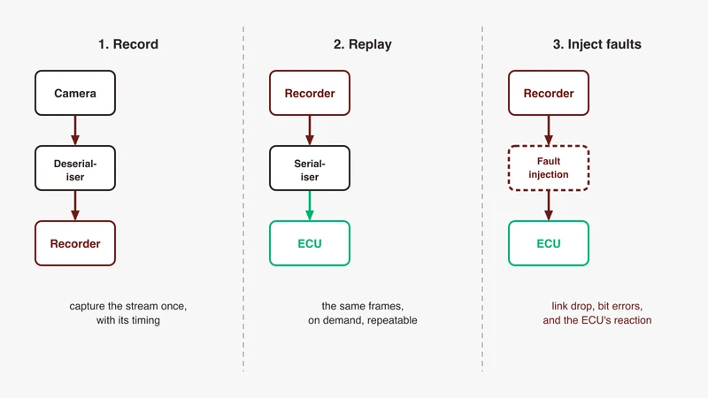
Record, replay, inject: the three workflows and when you need each
Record is for evidence: a deserialiser feeds a recorder and frames land with timestamps. Replay is for regression: a recorder feeds a serialiser driving the ECU’s deserialiser input, so the ECU sees a link rather than a file. Two things decide whether that works: the mode must match end to end, and the back channel must be answered, since the ECU configures and synchronises the camera it believes is present. Inject sits in the same path with a stage that can modify what passes. Equipment for all three is a market category of capture and replay platforms.
Aligning video frames with bus traffic on one timeline
A camera defect is rarely a camera defect. It is a camera frame, a CAN message and an Ethernet stream disagreeing about what happened, and only one timeline shows that. The camera side comes from recorder timestamps at the deserialiser output; the bus side usually arrives already wrapped, with a timestamp and an interface identifier, in a capture encapsulation format. The join is the clock under both, which is why gPTP synchronisation is a prerequisite here.
Bandwidth and storage reality check before you plan the campaign
Do the arithmetic before booking the vehicle, because uncompressed video at these rates fills media fast. Our companion article on data loggers and capturing without loss works the storage sums through in full; the point here is that the link rate is the input and the rate classes above are where it comes from. The GMSL vendor states approximately 9.7 Gbit/s of usable bandwidth on a 12 Gbit/s GMSL3 link, so a plan treating line rate as payload is wrong in the direction that hurts.
Fault injection: link drop, bit errors, back-channel loss, and the ECU’s reaction
Four cases belong in a plan: the link drops and returns, bits are corrupted while the link stays up, the back channel is lost while video continues, and video continues but the content is stale. The last two usually have no test case at all. The documented diagnostics are your instrumentation: CRC protection, back channel CRC error reporting, line fault detection and built-in self test on one family, decode and idle errors against FEC uncorrectable errors on the other. Whether your ECU software reads those registers is the thing under test.
Choosing for a programme
Questions to ask: silicon availability, second source, tooling, cable and connector supply
Put these in writing. Which family, generation and rate class is the camera module, and which is the ECU input? Is there a second source at that rate and qualification, and if not, what is the mitigation? What is the channel specification, and has our harness been measured against it? Which link mode does the module run? Which capture and replay platforms does your team already have working with this family, at what version?
Migration risk when the OEM changes family mid-programme
Changing generation inside a family is the cheaper case and still not free: pin compatibility and design reuse on one side, a stricter channel budget and changed error monitoring on the other. Changing family is expensive, because serialiser, deserialiser, driver stack, harness measurements and every piece of capture and replay equipment are family-specific, and test equipment is the item most often left out of that estimate.
What to prototype before the architecture freezes
Three things, all small. Prove one link end to end at the target generation and rate on the harness and connectors you will ship. Prove one record and one replay cycle into the real ECU with the back channel answered, because that is where benches fail. And prove one correlated capture: one camera stream and one bus stream, one timeline.
Where GSAS fits
GSAS Micro Systems is an engineering partner, and on SerDes camera paths the useful conversation happens before equipment is specified. Which family and generation the programme runs, whether the workflow you need is record, replay or injection, and what has to be true about the back channel and the link mode for the ECU to behave as it does in the vehicle: three answers that narrow a shortlist faster than a datasheet comparison.
Our applications engineers work in IST, and the teams we work with sit in Bengaluru, Pune, Chennai and Hyderabad. A camera-path scoping session is a working session: we go through your link, your ECU interface, your correlation requirement and your storage arithmetic, and tell you which of the questions above your quotations leave unanswered.
Start with the automotive Ethernet capability page, then request a scoped conversation describing your camera path and what you need to prove. Where the honest answer is that your bench already covers it, that is the answer you get.
References
- MIPI Alliance, A-PHY specification page (gears, reach, adaptation layers, packet error rate, IEEE 2977-2021): https://www.mipi.org/specifications/a-phy
- MIPI Alliance, CSI-2 specification page (D-PHY, C-PHY and A-PHY): https://www.mipi.org/specifications/csi-2
- Automotive SerDes Alliance, About ASA (founding, membership, Motion Link v1.01 to v2.1): https://auto-serdes.org/about-us/
- Automotive SerDes Alliance, “ASA Motion Link Specification 2.0 is here!”, 16 May 2024: https://auto-serdes.org/news/asa-motion-link-specification-2-0-is-here-944/
- Automotive SerDes Alliance, “ASA completes the first Automotive SerDes standard with integrated security”, 13 October 2020 (topologies, time base, cabling, security): https://auto-serdes.org/news/automotive-serdes-alliance-asa-completes-the-first-automotive-serdes-standard-with-integrated-security-325/
- Automotive SerDes Alliance, news and events index (plugfests, PMA test suite workshop): https://auto-serdes.org/
- Silicon vendor GMSL technology page (one channel for video, audio, control, data, power; ASIL B): https://www.analog.com/en/solutions/gigabit-mulitimedia-serial-link.html
- Silicon vendor SerDes and GMSL product category page (speeds up to 12 Gbit/s): https://www.analog.com/en/product-category/serdes-gmsl.html
- Silicon vendor application note AN-2615, “Upgrading GMSL2 to GMSL3” (rates, NRZ and PAM4, mandatory FEC, channel specifications): https://www.analog.com/en/resources/app-notes/an-2615.html
- Silicon vendor technical article, “Navigating GMSL: How Pixel and Tunnel Modes Enhance System Performance”, issue 235, June 2025 (generations, media, the two modes): https://www.analog.com/en/resources/analog-dialogue/raqs/raq-issue-235.html
- Silicon vendor FPD-Link SerDes overview page (uncompressed video, control and power on one cable; evaluation GUI): https://www.ti.com/interface/fpd-link-serdes/overview.html
- Silicon vendor FPD-Link III serialiser datasheet, SNLS552E, April 2024 (4.16 Gbit/s forward channel, 50 Mbit/s control channel, back channel frame, power over coax): https://www.ti.com/lit/ds/symlink/ds90ub953-q1.pdf
- Silicon vendor FPD-Link IV serialiser datasheet, SNLS750A, January 2025 (7.55 Gbit/s, 6 Gbit/s payload, D-PHY v2.1, pin compatibility): https://www.ti.com/lit/ds/symlink/ds90ub971-q1.pdf
- IEEE P802.3dm Project Authorization Request, approved 21 March 2024 (imaging sensors at end-nodes with a low-bandwidth backchannel): https://www.ieee802.org/3/dm/P802.3dm_PAR.pdf
- Linux kernel documentation, Media subsystem driver API (CSI-2 and camera sensor drivers, V4L2 sub-devices): https://docs.kernel.org/driver-api/media/index.html
Note on access: the analog.com pages refused automated fetches when this was written and were read through Internet Archive snapshots.
Also appears in:
Building for Automotive & Mobility?
Talk to our application engineers for personalized tool recommendations.