
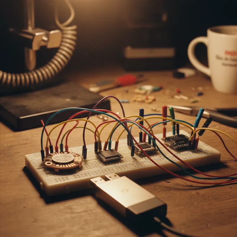
There is a category of embedded debugging that happens away from the bench. Customer site visits where reproducing a field failure means tapping into an I2C sensor and a UART console. Factory floors where an RS-485 segment needs watching during commissioning. Shared labs where every square centimetre of bench space is contested.
For those situations you want protocol coverage without an instrument trolley. The Binho Pulsar is Binho’s answer, and this guide covers exactly what it ships with today, taken from Binho’s own published specifications.
What Ships, and What Does Not
Binho splits the Pulsar’s feature list into what is available now and what is coming soon. It is worth reproducing that split plainly, because a lot of secondhand coverage of this product blurs it.
Available now: SPI Controller, I2C Controller, UART, RS-485, GPIO.
Coming soon, per Binho: SPI Peripheral, I2C Peripheral, I2C 10-bit addressing, CAN-FD (Binho’s figure is up to 5 Mbps, optimized for use in 12 V systems), 1-Wire, and GPIO PWM.
If you are evaluating the Pulsar for CAN-FD or 1-Wire work, that is the answer: not yet. GSAS will not specify the Pulsar into a test plan that depends on either. Everything below concerns the shipping feature set.
SPI at 50 MHz
Binho specifies the Pulsar’s SPI controller at 50 MHz with up to four chip-select signals, all four SPI modes, and configurable MSB or LSB bit order, at 1.2 V to 3.3 V. This is the same SPI controller specification Binho publishes for the Binho Supernova, and it is four times the 12 MHz maximum clock Binho lists for the older Binho Nova.
The practical consequence is flash work. Reading back a multi-megabyte SPI NOR image to verify a production write, or programming one in the first place, is dominated by clock rate. Four chip selects mean a board carrying a flash device plus an SPI-attached ADC or secure element can be exercised in one session without re-wiring between parts.
I2C at 1 MHz with Configurable Pull-Ups
The I2C controller is specified at 1 MHz with 7-bit addressing, clock stretching, and configurable pull-up resistors, again at 1.2 V to 3.3 V. Clock stretching support is not a checkbox: fuel gauges, smart battery packs and some PMICs stretch aggressively, and an adapter that mishandles it produces failures that look like wiring faults.
Configurable pull-ups are the quiet feature that saves the most time. A bench harness never reproduces the target board’s own bus loading, and being able to set the pull-up in software rather than soldering one onto a breakout is the difference between a quick check and a rework session.
Note the boundary here as well: Binho lists I2C 10-bit addressing and I2C Peripheral mode as coming soon. The Pulsar is a 7-bit I2C controller today.
UART at 115200 Baud
UART runs at up to 115200 baud with hardware flow control. That is the speed most embedded debug consoles actually run at, and the value of having it on this instrument is not the number, it is that the console and the buses sit behind the same USB connection so one session can correlate a printed message with the register state behind it.
One current limitation worth knowing: UART is not yet part of Mission Control 3’s protocol coverage on either the Pulsar or the Supernova. Mission Control 3 covers I2C, SPI and GPIO on the Pulsar, adding I3C on the Supernova. UART work goes through Mission Control 2 or the Python SDK for now.
RS-485: The Interface That Earns Its Place in India
RS-485 is the physical layer underneath Modbus RTU, PROFIBUS, and a long tail of proprietary industrial protocols. It is pervasive in Indian factory automation, building management, energy metering and solar inverter installations, where Modbus RTU remains the dominant fieldbus between PLCs, VFDs, HMIs and SCADA systems.
Binho specifies the Pulsar’s RS-485 interface as half-duplex with a -7 V to +12 V common-mode input range. That common-mode figure is the specification that actually matters in the field. Two panels thirty metres apart do not share a ground; they share a ground potential difference, and the common-mode range is what determines whether the receiver still resolves the differential signal through that offset. A jumper on a bench never tests this. A commissioning job in a plant does.
Because RS-485 here is differential signalling carrying what is fundamentally UART data, moving between console-level UART debugging and RS-485 fieldbus monitoring needs no additional hardware. Our dedicated guide on RS-485 and Modbus RTU testing with the Binho Pulsar walks through capture, injection and commissioning workflows in detail.
GPIO, Power and the Host Link
Six digital I/O pins, configurable as interrupts, at 1.2 V to 3.3 V. On a portable debug jig those pins become chip selects, target resets, rail enables and bring-up sequencing controls, which removes the breakout board that would otherwise travel with the adapter.
Downstream power is programmable from 1.2 V to 3.3 V, so a low-voltage peripheral rail can be brought up from the adapter itself during early debug. The host link is USB 2.0 High Speed at 480 Mbps over USB Type-C. Physically, Binho describes a compact, robust machined-aluminum enclosure with five RGB LEDs, two mounting holes with hardware included, and a custom protective zippered carry case.
Nova, Supernova, or Pulsar?
Briefly, on published specifications only. The Nova is Binho’s first-generation adapter: I2C to 3.4 MHz, SPI to 12 MHz, UART to 1 Mbps, 1-Wire, 5x shared GPIO, USB bus powered. The Supernova is the MIPI I3C instrument, specified as Controller or Target at 12.5 MHz with SDR and HDR-DDR, plus a 50 MHz SPI controller. The Pulsar is the one with RS-485 and programmable downstream power. The full side-by-side is in our Nova vs Supernova vs Pulsar comparison.
Why Buy from GSAS
GSAS Micro Systems is an authorized Binho engineering partner in India, supplying the Pulsar with INR invoicing and local logistics. Our applications engineers help teams select the right Binho instrument for their protocol requirements, and tell you plainly when the answer is that none of them fits yet. Contact GSAS from offices in Bengaluru, Hyderabad, Chennai, Pune, Mumbai, and Delhi NCR for evaluation units and guidance on deploying Binho adapters across your engineering organization.
Also appears in:
Interested in Binho tools?
Talk to our application engineers for personalized tool recommendations.
More from Binho
View all →
I3C FAQ for Firmware Teams: What the Bus Is, What Changes, and What You Need on the Bench
31 Jul · 8 min
Running the Binho Supernova as an I3C Target: Emulating a Device Against Your Own Controller
31 Jul · 7 min
Binho Mission Control 3 (Public Preview): Point-and-Click I2C, SPI, I3C, and GPIO
20 Jul · 5 min
Binho Mission Control: Point-and-Click I2C, SPI, and UART Without Writing Code
7 Apr · 5 min

Emulating Processor Power for Thermal Testing: Why Constant Power
7 Oct · 7 min

CRPS and Rack Power Supply Testing: The Six Tests That Matter
7 Oct · 7 min


