
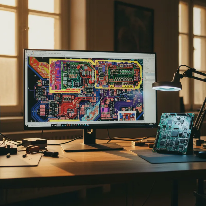
Power Supply Debugging with Sensepeek PCBite: Ripple, Transients, and Voltage Rail Testing
Power supply debugging is one of the most probe-intensive tasks in embedded hardware development. Measuring output ripple on a DC-DC converter requires stable, repeatable probe contact on small output capacitor pads. Capturing load transients requires the probe to be in position before the event occurs, you cannot hand-hold a probe and wait for a transient that happens in microseconds.
Validating multi-rail power sequencing requires simultaneous measurements on three or more voltage rails. The Sensepeek PCBite system addresses all three scenarios by keeping probes locked in position, hands-free, for as long as the measurement requires.
Why Power Supply Measurements Demand Hands-Free Probing
Power supply measurements differ from general signal debugging in several important ways:
Long observation windows. Ripple measurements often require running for seconds or minutes to capture worst-case conditions under varying load. Holding a probe tip on a 0402 capacitor pad for three minutes while monitoring an oscilloscope trace is impractical. PCBite probes stay positioned indefinitely.
Multi-point correlation. A typical embedded board has three to five regulated rails. Understanding how one rail’s dropout affects downstream rails requires simultaneous measurement. The PCBite kits provide six probe points, enough to instrument the input supply, two or three output rails, enable signals, and power-good flags in a single setup.
Probe-induced noise sensitivity. Ripple measurements at the millivolt level are sensitive to probe ground loop inductance. A dangling 15 cm ground clip lead on a traditional probe adds more noise to the measurement than the ripple you are trying to measure. PCBite probes use short ground springs that minimize ground loop area.
Measuring DC-DC Converter Output Ripple
Output ripple measurement is the most common power supply debug task. The goal is to verify that the ripple voltage on a regulated output stays within the specification, typically tens of millivolts on a well-designed converter.
Setup
- Mount the board on the PCBite base plate using the magnetic PCB holders.
- Position an SQ200 or SQ500 probe directly on the output capacitor’s positive pad.
The output capacitor is the correct measurement point, not a via several centimeters away, which adds trace inductance and distorts the ripple waveform. 3. Connect the probe’s ground spring to the capacitor’s ground pad or the nearest ground via. Keep the ground path as short as possible, preferably under 10 mm. 4.
Set your oscilloscope to AC coupling (to remove the DC offset and zoom in on the ripple), 20 mV/div or 50 mV/div vertical scale, and a time base that shows several switching cycles (typically 1-10 us/div for converters switching at 100 kHz to 2 MHz).
What to Look For
The ripple waveform on a buck converter typically shows a triangular component from the output inductor current ripple and high-frequency spikes at the switching transitions. The triangular component reflects the converter’s LC filter design. The spikes are caused by parasitic inductance in the current loop and are sensitive to PCB layout.
If the ripple amplitude exceeds the specification, common causes include insufficient output capacitance, high-ESR capacitors, poor PCB layout (long current loops), or an unstable feedback loop. The hands-free PCBite setup lets you swap capacitors, adjust feedback components, or modify load conditions while continuously monitoring the ripple, no need to re-establish probe contact after each change.
Capturing Load Transients
Load transient response, how the output voltage behaves when the load current steps up or down, is a critical power supply parameter. A microcontroller entering or exiting sleep mode, an RF transmitter keying on, or a motor starting can impose step-load changes that cause voltage excursions on the regulated rail.
Setup
Position the SQ200 or SQ500 probe on the regulator output, with ground connected locally as for ripple measurement. Set the oscilloscope to single-shot trigger mode, DC coupling, and edge trigger on the voltage channel. Set the trigger level just below or above the nominal output voltage (depending on whether you are capturing an undershoot or overshoot).
For a controlled test, use an electronic load with a step function. For an in-circuit test, trigger the load transient by toggling the system’s operating mode, for instance, commanding the microcontroller from sleep to active via a debug command.
The PCBite probe’s position stability is essential here. Load transient events last microseconds. You need the probe in position and the oscilloscope armed before the event occurs. With a hand-held probe, any slip during the wait period means re-arming and re-triggering.
Multi-Rail Sequencing Validation
Boards with SoCs, FPGAs, or complex PMICs require specific power-up and power-down sequencing. Rails must reach regulation in a defined order, with defined timing margins between them. Incorrect sequencing can cause latch-up, ESD damage to internal structures, or failure to boot.
Setup
Position six PCBite probes, two SQ200 or SQ500 probes on the two most critical rails, and four SQ10 probes on remaining rails, enable inputs, and power-good outputs. Connect SQ200/SQ500 probes to oscilloscope channels and SQ10 probes to logic analyzer or scope channels with DC coupling.
Trigger on the system enable signal (or the first rail’s output exceeding a threshold) and capture the full power-up sequence in a single acquisition. Measure the time between each rail reaching regulation, compare against the PMIC or SoC datasheet requirements, and verify that power-good signals assert in the correct order.
For hardware teams in Bengaluru and Pune bringing up FPGA or SoC platforms, this six-point sequencing measurement setup, built once and reused across every board revision and every power-on test, eliminates the most time-consuming part of power supply validation.
Voltage Rating Considerations
The SQ200 and SQ500 are rated at 300V RMS CAT II, making them suitable for measurements on offline AC-DC converters and high-voltage industrial power supplies. For typical embedded board rails (1.0 V to 12 V), the voltage rating provides ample headroom. The SQ10 is rated at ±60 V DC, which covers most embedded logic-level rails and enable signals.
The SQ-series probes’ insulated bodies add a safety margin when probing near high-voltage nodes on mixed-voltage boards, a practical benefit for power electronics work in labs across Hyderabad, Chennai, and Mumbai.
Bandwidth Selection for Power Measurements
For output ripple on converters switching below 2 MHz, the SQ200’s 200 MHz bandwidth is more than sufficient, you are capturing a signal with fundamental content below 10 MHz and harmonics extending to perhaps 50-100 MHz.
For converters using GaN or SiC switches with sub-nanosecond transitions, the SQ500 provides better fidelity on the switching transient edges. The SQ500’s lower 9 pF input capacitance also produces less loading on high-impedance feedback divider networks.
Why Buy from GSAS
GSAS is an authorized engineering partner in India, providing PCBite kits and probes alongside oscilloscopes and power analyzers for complete power supply debug setups. Our application engineers in Bengaluru, Hyderabad, Chennai, Pune, Mumbai, and Delhi NCR help teams select the right PCBite probe combination for their power supply measurement requirements and integrate Sensepeek probes with their existing test instrumentation. Contact GSAS for pricing and application guidance.
Also appears in:
Interested in Sensepeek tools?
Talk to our application engineers for personalized tool recommendations.
More from Sensepeek
View all →
Shrinking Boards, Growing Problems: Why Hands-Free Probing Is Essential as Component Density Rises
7 Apr · 4 min
Getting Started with Sensepeek PCBite: Unboxing to First Measurement
7 Apr · 5 min
High-Speed Interface Validation with Sensepeek SQG Probes: USB, HDMI, and SATA
7 Apr · 5 min
6 Simultaneous Probe Points: Multi-Point Measurement with Sensepeek PCBite
7 Apr · 4 min

Emulating Processor Power for Thermal Testing: Why Constant Power
7 Oct · 7 min

CRPS and Rack Power Supply Testing: The Six Tests That Matter
7 Oct · 7 min


