
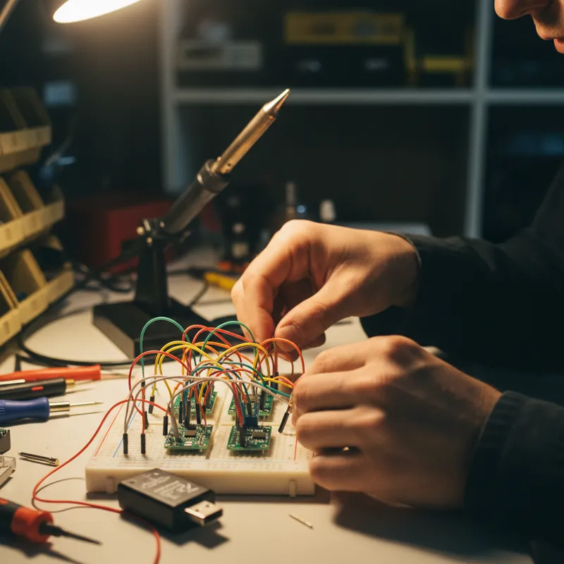
Bringing up an I3C sensor for the first time is a different experience from I2C. With I2C, the workflow is mechanical: look up the slave address in the datasheet, send a register read, confirm the WHO_AM_I value, and proceed. With I3C, the bus initialization itself requires a sequence of protocol-level operations, dynamic address assignment, capability discovery, and Common Command Code (CCC) configuration, before the first application-level register read can happen.
This guide walks through the I3C sensor bring-up process using the Binho Supernova as the I3C controller, covering the steps from physical connection through verified sensor communication.
Hardware Setup
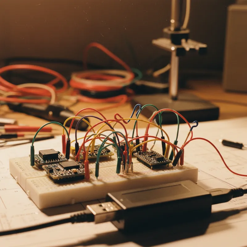
Connect the Supernova’s I3C port to the sensor target board. The I3C bus requires three connections: SCL, SDA, and GND. Unlike I2C, I3C operates in push-pull mode (not open-drain) during data phases, so external pullup resistors are not required for the push-pull segments. However, the bus begins in open-drain mode during initialization, and the Supernova provides configurable pullup capability for this phase.
Verify that the sensor target board’s I3C lines are at the correct voltage level. Binho publishes an I3C voltage range of 0.8 V to 3.3 V for the Supernova, which is lower than the 1.2 V to 3.3 V it specifies for the same instrument’s I2C, SPI, UART and GPIO pins. Many I3C sensors target 1.8 V I/O; confirm this matches the Supernova’s configured I/O voltage before powering up. If you are new to the bus itself, our I3C FAQ for firmware teams answers the fundamentals first.
If the target board also has I2C devices on the same bus (a mixed I2C/I3C configuration), the Supernova handles this, I3C is backward compatible with I2C targets, and the Supernova identifies I2C-only devices separately during bus initialization.
Step 1: Bus Scan and Device Discovery
Launch Mission Control and connect to the Supernova. The first operation is a bus scan that discovers all devices present on the I3C bus.
The Supernova performs bus initialization by sending a RSTDAA (Reset Dynamic Address Assignment) broadcast CCC to clear any previously assigned addresses, followed by an ENTDAA (Enter Dynamic Address Assignment) sequence. During ENTDAA, each I3C target on the bus responds with its 48-bit Provisioned ID (PID), Bus Characteristics Register (BCR), and Device Characteristics Register (DCR). The Supernova collects these identifiers and assigns a 7-bit dynamic address to each target.
Mission Control displays the discovered devices in a table showing:
- Provisioned ID: 48-bit unique identifier (manufacturer ID + part ID + instance ID). This is the I3C equivalent of a silicon serial number.
- BCR: indicates the device’s capabilities: maximum data speed, IBI support, controller role capability, offline capability, and virtual target support.
- DCR: a device type code defined by MIPI Alliance (e.g., accelerometer, gyroscope, temperature sensor, pressure sensor).
- Assigned Dynamic Address: the 7-bit address the Supernova assigned during DAA.
If no devices appear, verify power, voltage levels, and physical connections. If the sensor only supports I2C legacy mode, it will not respond to ENTDAA, use the Supernova’s I2C scan mode to detect it at its static address.
Step 2: Reading Device Capabilities with CCC Commands
With dynamic addresses assigned, the next step is reading each target’s capabilities using directed CCC (Common Command Code) commands. The Supernova’s Mission Control GUI provides a CCC command interface where engineers can send any standard CCC and inspect the response.
GETMWL (Get Max Write Length) returns the maximum number of bytes the target can accept in a single private write transfer. This determines how firmware should chunk configuration register writes.
GETMRL (Get Max Read Length) returns the maximum bytes the target can return in a single private read. For sensors that output multi-byte data frames (accelerometer X/Y/Z triplets, barometric pressure + temperature readings), this value determines whether the data fits in one transfer or requires multiple reads.
GETPID (Get Provisioned ID) retrieves the 48-bit PID, which can be used to identify the specific sensor part number and silicon revision from the MIPI Alliance device registry.
GETCAPS (Get Capabilities) returns detailed capability information beyond what BCR and DCR provide, including supported HDR modes, maximum SDR and HDR data rates, and timing specifications.
These CCC responses validate that the sensor’s I3C peripheral is functioning correctly and provide the parameters needed to configure optimal transfer sizes and speeds.
Step 3: Private Read/Write Transfers
With device capabilities confirmed, application-level communication begins. I3C private transfers are the equivalent of I2C register reads and writes, they send and receive data to a specific target using its dynamic address.
To read a sensor’s device ID register, send a private write with the register address byte, followed by a private read for the expected number of response bytes. In Mission Control, this is a two-step operation: write the register address, then read the response. In the Python SDK, it is a single function call that handles the write-then-read sequence.
Verify the device ID matches the sensor datasheet. This confirms that the full communication chain, physical connection, bus initialization, dynamic addressing, and data transfer, is working correctly. From this point, all sensor configuration and data readout follows the same private transfer pattern, using register addresses from the sensor’s datasheet.
Step 4: Configuring and Handling In-Band Interrupts
For sensors that support data-ready interrupts, I3C’s In-Band Interrupt (IBI) mechanism eliminates the need for a dedicated IRQ line. The sensor asserts an interrupt directly on the SDA line during the bus idle phase, and the controller acknowledges and reads the interrupt payload.
To enable IBIs on a specific target, send the ENEC (Enable Events Command) directed CCC to that target’s dynamic address with the IBI enable bit set. The Supernova then monitors the bus for IBI assertions.
When the sensor triggers an IBI (for example, when a new accelerometer sample is ready), Mission Control displays the interrupt event with a timestamp, the source target’s address, and any mandatory data bytes (MDB) the target transmitted as part of the IBI. The MDB typically indicates the interrupt source, data ready, FIFO threshold, or error condition, allowing the controller to determine the appropriate response without polling a status register.
In the Python SDK, IBI events are delivered through a callback mechanism, enabling automated test scripts that wait for sensor data-ready interrupts, read the data, and validate the values against expected ranges.
Step 5: Exploring HDR-DDR Mode
If the sensor supports HDR-DDR (check the GETCAPS response), the Supernova can switch the bus to HDR-DDR mode for higher-throughput data transfers. HDR-DDR transmits data on both clock edges, doubling the effective data rate compared to SDR at the same clock frequency.
From Mission Control, initiate an HDR-DDR transfer to the target and verify that data integrity is maintained. HDR-DDR mode uses a different framing protocol than SDR, with CRC protection on each data word, the Supernova validates CRC automatically and flags any errors.
HDR-DDR is particularly relevant for sensors that output high-volume data streams: multi-axis IMUs at high sample rates, time-of-flight sensors, and audio codecs where the additional bandwidth reduces bus occupancy and frees time for other targets.
Common Bring-Up Issues
Target does not respond to ENTDAA. Verify that the sensor’s I3C peripheral is enabled (some sensors require a configuration pin or register write to switch from I2C-only to I3C mode). Check voltage levels, I3C targets are sensitive to I/O voltage mismatches.
BCR indicates no IBI support. Not all I3C targets implement IBI. Some early I3C sensors only support polled operation, with IBI planned for future silicon revisions. Check the sensor datasheet for IBI capability.
Private transfers return unexpected data. Confirm the register map in the datasheet corresponds to I3C mode, some sensors have different register layouts or addresses in I3C mode compared to I2C mode.
Why Buy from GSAS
GSAS Micro Systems is an authorized Binho engineering partner in India, providing the Binho Supernova, Binho Nova, and Binho Pulsar with INR invoicing and I3C application engineering support. Our team helps engineering organizations across India navigate I3C adoption, from initial sensor bring-up through production test fixture development. Contact GSAS from offices in Bengaluru, Hyderabad, Chennai, Pune, Mumbai, and Delhi NCR for evaluation units, I3C workshop delivery, and hands-on protocol support.
Also appears in:
Interested in Binho tools?
Talk to our application engineers for personalized tool recommendations.
More from Binho
View all →
I3C FAQ for Firmware Teams: What the Bus Is, What Changes, and What You Need on the Bench
31 Jul · 8 min
Running the Binho Supernova as an I3C Target: Emulating a Device Against Your Own Controller
31 Jul · 7 min
Binho Mission Control 3 (Public Preview): Point-and-Click I2C, SPI, I3C, and GPIO
20 Jul · 5 min
Binho Mission Control: Point-and-Click I2C, SPI, and UART Without Writing Code
7 Apr · 5 min

Emulating Processor Power for Thermal Testing: Why Constant Power
7 Oct · 7 min

CRPS and Rack Power Supply Testing: The Six Tests That Matter
7 Oct · 7 min


