

PCBite Hands-Free Probing: Why Engineers Are Switching from Clip-On Leads
Every embedded hardware engineer has experienced it: holding an oscilloscope probe in one hand, a ground clip in the other, trying to simultaneously read a waveform on screen while the probe tip slips off a 0.5 mm test pad. The traditional approach to PCB probing, clip leads, alligator clips, and manually held probe tips, works until you need precision, repeatability, or more than two measurement points at once.
The Sensepeek PCBite system addresses this fundamental workflow problem with a different approach: a magnetic base plate, articulating probe holders, and spring-loaded needle tips that stay exactly where you place them.
How the PCBite System Works
The foundation of every PCBite setup is a mirror-polished stainless steel base plate in DIN A4 format (297 x 210 mm). The board under test sits on CNC-machined anodized aluminum PCB holders, four come in each kit, which use powerful magnets to lock the board in position. The dual-sided base plate provides a matte surface for reduced glare during normal debugging and a mirror-polished surface for bottom-side board inspection.
Each probe mounts into an articulating arm with a magnetic base. You position the probe tip over your target pad, let the magnet lock the arm in place, and the spring-loaded needle maintains consistent contact pressure. Once positioned, the probes stay put. You can walk away, come back, and the measurement setup is exactly as you left it.
This matters more than it sounds. When debugging a power sequencing issue on a multi-rail design, you might need to monitor VCC, a clock signal, a reset line, and a data bus simultaneously. With traditional probes, setting up four stable contact points is an exercise in frustration. With PCBite, each probe holds its position independently.
The Probe Lineup
Sensepeek offers probes across a wide bandwidth range, all sharing the same magnetic mounting system:
SQ10: The general-purpose 1:1 passive probe with 10 MHz bandwidth. Designed for DC voltage measurements, low-frequency signal observation, and logic analyzer connections. The SQ10 connects via Dupont and banana plug test wires to oscilloscopes, multimeters, and logic analyzers. Rated at ±60 V DC / 30 V AC RMS with 200 V overvoltage protection and 2 A DC current capacity through the probe tip.
SQ200: A 200 MHz passive 10:1 oscilloscope probe with 10 M-ohm input impedance and 13.9 pF input capacitance. The SQ200 covers the majority of embedded debugging scenarios: SPI clock validation, I2C bus integrity, PWM waveforms, and UART signal quality. The 300V RMS CAT II rating makes it suitable for power supply and motor drive measurements.
SQ500: The highest-bandwidth SQ-series probe at 500 MHz with just 9 pF input capacitance. The SQ500 captures USB 2.0, LVDS, MIPI interfaces, and fast switching transients with minimal signal distortion.
All SQ-series probes feature fully insulated bodies for dual-mode operation, hands-free on the magnetic base plate or handheld for quick spot checks. Every probe uses the same 0.5 mm spring-loaded exchangeable test needle, so replacement tips work across the entire SQ family.
Complete Kits vs. Individual Probes
Sensepeek packages the PCBite system in three kit configurations, each including the base plate, four PCB holders, test wires, replacement needles, and insulation accessories:
- PCBite Kit with 4x SQ10: The entry point for teams starting with logic analyzer and multimeter measurements.
- PCBite Kit with 2x SQ200 + 4x SQ10: Adds 200 MHz oscilloscope capability for general embedded debugging.
- PCBite Kit with 2x SQ500 + 4x SQ10: The premium configuration for high-speed digital and mixed-signal work.
Individual probes can be added to any kit at any time, they all share the same magnetic mounting standard.
Practical Impact on the Debug Workflow
The hands-free aspect changes the debugging workflow in subtle but meaningful ways. When probes hold their position, you can focus on adjusting oscilloscope trigger settings, changing firmware parameters, or reviewing schematics without constantly re-establishing probe contact. Multi-channel measurements become practical rather than heroic.
And because the spring-loaded needles maintain consistent contact pressure, measurement repeatability improves, the same pad produces the same waveform characteristics session after session.
For teams doing production-line bring-up or incoming inspection, the repeatability advantage compounds. A test setup configured once on the PCBite base plate can be reused by different technicians without re-training on probe positioning.
Why Buy from GSAS
GSAS is an authorized engineering partner in India, providing the full PCBite product range with INR invoicing, local inventory, and application support. Our engineers in Bengaluru, Hyderabad, Chennai, Pune, and Mumbai help teams select the right kit configuration and integrate Sensepeek probes into existing test setups. Whether you need a single SQ10 kit for a prototype lab or volume quantities for a production floor, GSAS provides evaluation units, technical guidance, and responsive support across India. Contact GSAS for pricing and availability.
Also appears in:
Interested in Sensepeek tools?
Talk to our application engineers for personalized tool recommendations.
More from Sensepeek
View all →
Shrinking Boards, Growing Problems: Why Hands-Free Probing Is Essential as Component Density Rises
7 Apr · 4 min

Getting Started with Sensepeek PCBite: Unboxing to First Measurement
7 Apr · 5 min
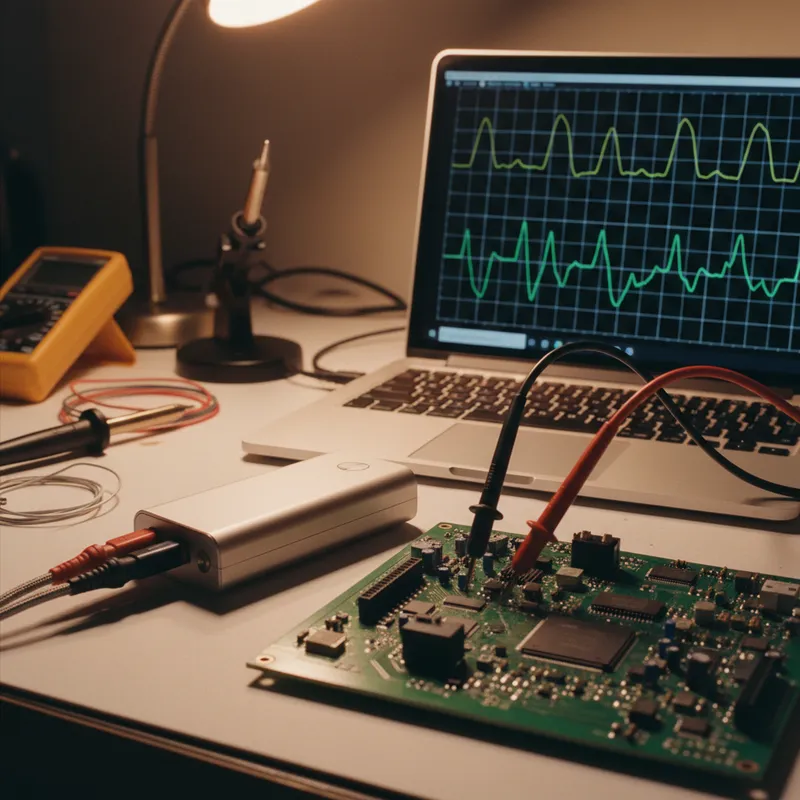
High-Speed Interface Validation with Sensepeek SQG Probes: USB, HDMI, and SATA
7 Apr · 5 min
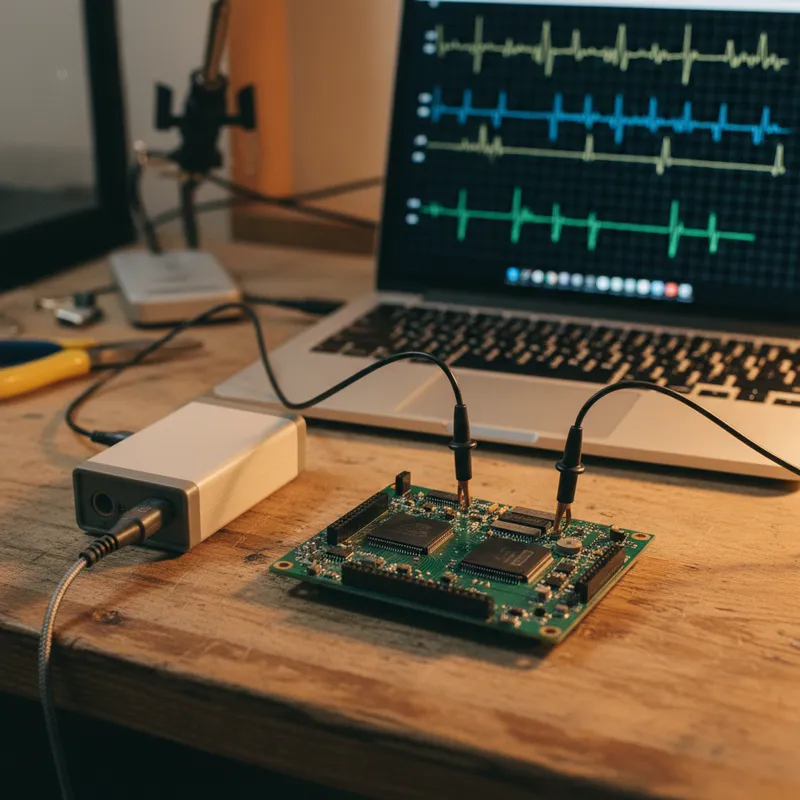
6 Simultaneous Probe Points: Multi-Point Measurement with Sensepeek PCBite
7 Apr · 4 min

Emulating Processor Power for Thermal Testing: Why Constant Power
7 Oct · 7 min

CRPS and Rack Power Supply Testing: The Six Tests That Matter
7 Oct · 7 min


