
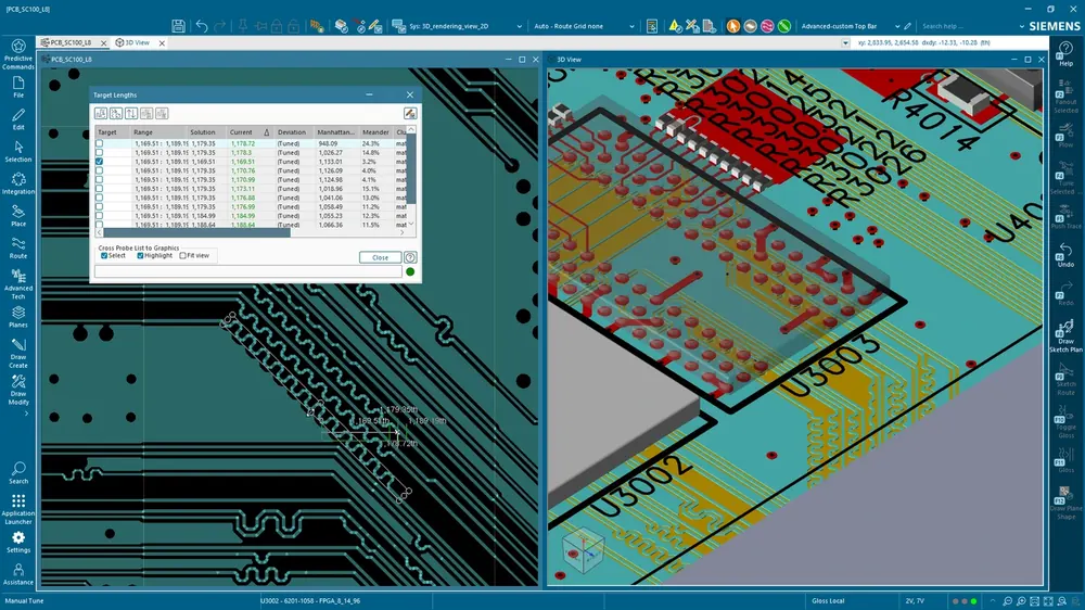
PCB design teams in India increasingly run into a familiar problem: their boards are getting more complex, signal integrity (SI) and power integrity (PI) issues are no longer optional concerns, but a permanent HyperLynx SI license sits idle for half the year. Siemens EDA’s Xpedition token system solves exactly this problem, pay only for the verification capabilities you actually use, when you actually use them, on top of a base Xpedition Standard subscription.
This post breaks down what the token system is, which add-ons are available, and how Indian engineering teams use it to keep enterprise-grade verification accessible at SMB-scale licensing costs.
What Are Xpedition Tokens?
Xpedition Standard ships with the core PCB design environment, schematic capture, constraint-driven routing, AI-infused workflow, cloud DFM via Valor NPI (12 runs/year included), and ECAD-MCAD co-design. Most Indian product teams designing 4-layer to 16-layer boards have everything they need without going further.
Tokens are how Xpedition Standard scales beyond the base subscription. You buy a pack of tokens, say a 25-token pack or a 50-token pack, and consume them as needed when you launch a specific verification flow. Each Value-Based License (VBL) capability has a documented per-use token cost. When you finish the flow, the tokens that capability consumed are committed. The remaining pool stays available for future use across your team.
The packs are floating licenses, so a single 25-token pack can be shared across multiple engineers in the same office, whoever needs HyperLynx pre-layout SI for an afternoon’s stackup exploration can pull tokens from the pool, run the analysis, and free the rest for the next person.
Available Token-Based Add-Ons
Today’s Xpedition Standard token catalog includes:
| Add-on | Token cost | Use case |
|---|---|---|
| Pre-Layout SI via HyperLynx LineSim | 15 tokens | Topology exploration, terminator selection, stackup decisions before routing begins |
| Post-Layout SI via HyperLynx BoardSim | 25 tokens | DDR4/DDR5, PCIe, Ethernet, USB compliance verification on the routed board |
| Rigid-Flex Design | 10 tokens | Bend regions, stackup zones, and 3D bend visualization for flex circuits |
| Advanced ECAD-MCAD Integration (NX) | 15 tokens | Tight Siemens NX co-design beyond the standard IDX format exchange |
The catalog continues to expand with each Siemens EDA release. The 2510 release added the Advanced ECAD-MCAD VBL. Future releases are expected to add formal verification, DRC extensions, and additional analysis flows.
Why Pre-Layout HyperLynx Matters
Most signal integrity issues are decided before a single trace is routed. The choice of stackup, the dielectric material, the trace impedance target, the placement of memory ICs relative to the controller, and the topology decisions for high-speed buses all happen at the pre-layout stage, when the schematic is done and the layout team is about to start. Mistakes made here are expensive to fix later because they require re-routing or, worse, re-spinning the board.
HyperLynx LineSim lets you model the proposed topology, run pre-route simulations on the critical nets (DDR4 address/command, PCIe Gen3/Gen4 differential pairs, USB 3.x), and answer questions like:
- Will this DDR4 fly-by topology work at 1600 MT/s, or do I need clamshell?
- Does this trace impedance need to be 45Ω or 50Ω given the stackup?
- Can I get away with 4-layer for this Ethernet design, or do I need 6-layer for clean reference planes?
These questions used to require either an expensive permanent SI license or a Field Application Engineer visit. The token system makes them answerable in an afternoon, billable to whichever project budget is funding the verification.
Why Post-Layout HyperLynx Matters
After the board is routed, HyperLynx BoardSim runs the same nets through full electromagnetic field-solver-based simulation on the actual layout. This catches the issues pre-layout couldn’t predict, coupling between adjacent nets, return-path discontinuities under split planes, via stub effects, and timing budget violations introduced during routing.
For high-speed digital interfaces, post-layout verification is the difference between “the board works” and “the board works at the corner cases your customers will run into in production.” DDR4/DDR5 designs in particular rely on tight timing margins where a 50 ps degradation can break an entire interface, well within the variation a poorly-routed via stub can introduce.
The 25-token cost of a post-layout BoardSim run reflects its complexity: it consumes more compute, it runs more analyses, and it produces more actionable findings. But spread across a 25-token or 50-token pack, even a small team can run post-layout on every critical interface for every board they ship.
Why the Token Model Works for Indian Teams
The token system is particularly well-suited to the Indian embedded design ecosystem for three reasons:
First: most Indian PCB design teams are 2-10 engineers. They cannot economically justify a permanent HyperLynx SI license that sits idle 60-70% of the year. The token system aligns the cost of verification with the cadence of actual project verification needs, a high-density board this quarter, nothing for the next two quarters, two boards next quarter.
Second: project budgets in India tend to be allocated at the project level, not the team level. The token model lets a project manager fund a specific verification effort out of that project’s budget. When the project ships, the remaining tokens roll into the team’s shared pool for the next project that needs them.
Third: the Xpedition technology continuum means tokens carry forward as your team grows. If your team eventually scales to 15+ engineers and you outgrow the token model, you can move to Xpedition Enterprise with a permanent HyperLynx license, same data format, same trained engineers, same constraint files, no migration disruption. The token system isn’t a dead end. It’s a scaling step.
How Indian Teams Adopt the Token System with GSAS
GSAS Micro Systems is an authorized Siemens EDA engineering partner in India. Our applications engineering team has supported PCB design teams across Bengaluru, Hyderabad, Chennai, Pune, Mumbai, Delhi NCR, Coimbatore, Visakhapatnam, Vadodara, and Kolkata through Xpedition Standard adoption with the token model. Typical engagements look like:
- Stackup review: our SI engineers work with your team to decide the right stackup for your board, layer counts, dielectric materials, and impedance targets, before any routing begins
- Pre-layout HyperLynx LineSim training: hands-on workshop on running pre-layout topology exploration on your actual high-speed nets
- Post-layout HyperLynx BoardSim sign-off: we walk through your routed board, run BoardSim on the critical nets, and document findings
- Token pack sizing: we help size the right token pack for your team based on board complexity and verification cadence
Try Xpedition Standard with HyperLynx SI Tokens
If you’re currently designing PCBs in a tool that doesn’t have integrated SI verification, or you’re paying for a permanent HyperLynx license and looking for a more cost-aligned model, the Xpedition Standard 30-day trial is the right starting point. The trial includes the full Xpedition Standard environment plus token allocations for HyperLynx LineSim and BoardSim, enough to verify a real critical interface on a real board and see what the workflow feels like.
For a deeper look at the Xpedition Standard virtual tour and the broader Siemens EDA partnership in India, see our Xpedition Standard product page or the Siemens EDA partner page.
Further Reading
- Xpedition Standard product page, full Xpedition Standard details, tokens, virtual tour
- HyperLynx product page, signal integrity, power integrity, electrical DRC
- Choosing the right Siemens EDA tier, Standard vs Enterprise decision framework
- Xpedition Standard virtual tour, interactive product walkthrough
- Migration to Xpedition, guide for teams switching from PADS or other PCB tools
- Siemens EDA partnership, full GSAS authorized partner page
Source material: This post is based on Siemens EDA’s published documentation on the Xpedition Standard token system, including the March 2026 Siemens blog post on Xpedition add-ons and HyperLynx signal integrity. All technical claims about token costs and add-on capabilities are sourced from official Siemens documentation.
Also appears in:
Interested in Siemens EDA tools?
Talk to our application engineers for personalized tool recommendations.
More from Siemens EDA
View all →
India's EDA Moment: Why Design Tool Demand Is Growing, and the Engineering Careers It Creates
21 Sept · 9 min

AI and Complexity Are Redrawing EDA: Siemens on the Trillion-Transistor Era
13 Sept · 6 min

Calibre Vision AI: Bringing Order to DRC Debug at Advanced Nodes
24 Aug · 4 min

Siemens EDA EBS Expert Series: 6 Free PCB Design Webinars (Jul-Aug 2026)
20 Jul · 8 min

Emulating Processor Power for Thermal Testing: Why Constant Power
7 Oct · 7 min

CRPS and Rack Power Supply Testing: The Six Tests That Matter
7 Oct · 7 min


