
Flex and rigid-flex PCBs are no longer exotic. Wearable medical devices, IoT sensors, foldable consumer electronics, drone flight controllers, and automotive sensor modules all increasingly use flex circuits to fit electronics into shapes a rigid PCB cannot. But Indian product teams adopting flex for the first time hit a familiar set of New Product Introduction (NPI) traps: bend radius failures, copper crack at the rigid-flex interface, signal integrity degradation across the flex section, and, for high-voltage designs, creepage and clearance violations that fail safety certification.
This post covers the three Siemens EDA capabilities that address these issues for Indian SMB design teams: Valor NPI cloud DFM, automated electrical creepage checking via HyperLynx DRC, and Xpedition Standard’s rigid-flex design support with bend region modeling.
Why Flex and Rigid-Flex NPI Goes Wrong
Flex circuit failures in production rarely happen because the circuit itself was wrong. They happen because the manufacturing constraints weren’t checked at design time:
- Bend radius too tight: copper layers crack on flex during assembly bending. Manufacturer rejects the panel. NPI slips by 4-6 weeks.
- Stiffener placement violates flex zones: the rigid stiffener overlaps the bend area. Mechanical assembly cannot fold the board cleanly.
- Trace routing perpendicular to bend axis: traces crack at the bend after a few flex cycles. Reliability failure in field, often months after delivery.
- Coverlay opening misaligned with pads: solder mask gaps don’t match component placement. SMT assembly yield drops.
- Creepage and clearance violations between high-voltage and low-voltage nets, fails IEC 60601 (medical), IEC 62368 (consumer), or ISO 26262 (automotive) electrical safety review.
Each of these is catchable at the design stage with the right tooling. And each, if missed, costs an Indian SMB team weeks of NPI time and tens of lakhs of rupees in scrapped panels and assembly setups.
Valor NPI: Cloud DFM for Flex and Rigid-Flex
Valor NPI is Siemens EDA’s cloud-based DFM (Design For Manufacturing) verification tool. Xpedition Standard subscriptions include 12 cloud DFM runs per year at no extra cost, enough for most Indian SMB teams to verify every board they ship before sending Gerbers to fabrication.
For flex and rigid-flex specifically, Valor NPI checks:
- Bend region clearances: that no components, vias, or stiffeners encroach into the bend area
- Trace orientation: flagging traces that cross the bend axis perpendicular (high crack risk) vs running parallel (safe)
- Layer transitions: verifying that the rigid-to-flex transition has the right number of pre-preg layers and the correct copper weight
- Coverlay opening alignment: that the flexible coverlay film has openings that match the component pad shapes
- Stack-up validation: that the rigid section stack-up and flex section stack-up are documented correctly for your fabricator
The cloud-based runs are fast (typically minutes for a complex board) and produce actionable findings with click-through to the offending location in the layout. Indian teams typically run Valor before sending Gerbers to AT&S India, Shogini, Genus, or any other domestic flex fabricator, the report becomes the handoff document that prevents the back-and-forth iteration that traditionally adds 2-3 weeks to flex NPI cycles.
Automated Creepage Checking via HyperLynx DRC
For high-voltage designs, EV battery management, motor drives, medical defibrillators, AC-DC power supplies, electrical creepage and clearance are safety-certification-critical. International standards (IEC 60601, IEC 62368, IEC 61010, UL 61800) all specify minimum physical distances between conductors at different potentials, computed from the working voltage, the pollution degree, the material group of the substrate, and the altitude of the operating environment.
Manually verifying creepage on a complex high-voltage board is tedious and error-prone. Miss one violation and the safety lab will catch it during certification, usually 3-4 months into the project, forcing a re-spin.
HyperLynx DRC automates this. The tool reads your board’s net classification (which nets are high-voltage, which are low-voltage), the working voltages between net classes, and your target standard. It then runs an exhaustive geometric check of every conductor pair on every layer and flags any clearance below the required minimum. Edge-to-edge, edge-to-via, edge-to-pad, plane-to-plane, all checked automatically, with the violating geometry highlighted in the layout.
For a typical Indian high-voltage design, an EV BMS board, a 3-phase motor drive, a medical-grade isolated power supply, automated creepage checking turns a 2-day manual review into a 5-minute automated run. The Siemens whitepaper Accelerating Safety Standards Compliance: Automating Creepage Checking walks through the methodology in detail, recommended reading for any Indian team designing for IEC 60601, IEC 62368, IEC 61010, or related standards.
Xpedition Standard Rigid-Flex Support
The base Xpedition Standard subscription includes flat-board PCB design. Adding the Rigid-Flex token VBL enables the dedicated rigid-flex modeling environment:
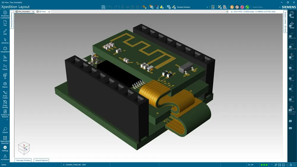
- Bend region definition: explicitly mark which portions of the board are bendable, with bend axis and bend radius as first-class design parameters
- Distinct stackup zones: the rigid section uses one stackup, the flex section uses another, the rigid-to-flex transition uses a third (with appropriate pre-preg). Xpedition Standard models all three zones in the same design file.
- 3D bend visualization: interactively fold the board in 3D to verify the assembled mechanical fit. Catches enclosure interference and folding-collision issues before fabrication.
- Bend stiffener modeling: place adhesive stiffener material on the flex side opposite from the bend region. Ensures the bend zone stays clean.
The Rigid-Flex VBL is a 10-token consumption per use, so a small team with a 25-token pack can run rigid-flex verification multiple times per project as the design iterates.
Why GSAS for Indian Flex and Rigid-Flex Adoption
GSAS Micro Systems is an authorized Siemens EDA engineering partner in India. Our applications engineering team has supported flex and rigid-flex adoption across Indian wearable, IoT, drone, medical, and EV teams. Typical engagements include:
- Pre-design review: stackup decisions, bend region planning, and component placement strategy before any layout begins
- Valor NPI walkthrough on your first flex board, interpreting cloud DFM findings, fixing them in Xpedition, re-running until clean
- Creepage automation setup: configuring HyperLynx DRC for IEC 60601 / IEC 62368 / IEC 61010 / ISO 26262 net classifications on your specific board
- Rigid-flex 3D bend verification: walking through the fold sequence on the assembled prototype enclosure
- Indian fabricator handoff: packaging the Valor + HyperLynx DRC reports for AT&S India, Shogini, Genus, or your fab of choice
Our engineers have spent years inside Xpedition + HyperLynx + Valor on real product programs in Bengaluru, Hyderabad, Chennai, Pune, Mumbai, Delhi NCR, Coimbatore, Visakhapatnam, and Vadodara.
Try Xpedition Standard with Rigid-Flex Support
The Xpedition Standard 30-day trial includes the base environment plus token allocations for the Rigid-Flex VBL, enough to model a real flex section, run bend visualization, and verify the design with Valor NPI. Combined with HyperLynx DRC (token-based) and the standard pre-/post-layout SI add-ons, the trial covers the full flex NPI workflow.
Further Reading
- Xpedition tokens and HyperLynx signal integrity deep-dive
- Scaling PCB design with adaptable add-ons (webinar)
- Xpedition Standard product page
- HyperLynx product page
- Valor NPI cloud DFM product page
- Choosing the right Siemens EDA tier
- Migration to Xpedition
- Siemens EDA partnership
Source material: Siemens EDA whitepaper Accelerating Safety Standards Compliance: Automating Creepage Checking and the Xpedition Standard rigid-flex documentation. Trial CTAs use the GSAS partner-attribution URL with utm_source=gsasindia.
Also appears in:
Interested in Siemens EDA tools?
Talk to our application engineers for personalized tool recommendations.
More from Siemens EDA
View all →
India's EDA Moment: Why Design Tool Demand Is Growing, and the Engineering Careers It Creates
21 Sept · 9 min

AI and Complexity Are Redrawing EDA: Siemens on the Trillion-Transistor Era
13 Sept · 6 min

Calibre Vision AI: Bringing Order to DRC Debug at Advanced Nodes
24 Aug · 4 min

Siemens EDA EBS Expert Series: 6 Free PCB Design Webinars (Jul-Aug 2026)
20 Jul · 8 min

Emulating Processor Power for Thermal Testing: Why Constant Power
7 Oct · 7 min

CRPS and Rack Power Supply Testing: The Six Tests That Matter
7 Oct · 7 min


