In short
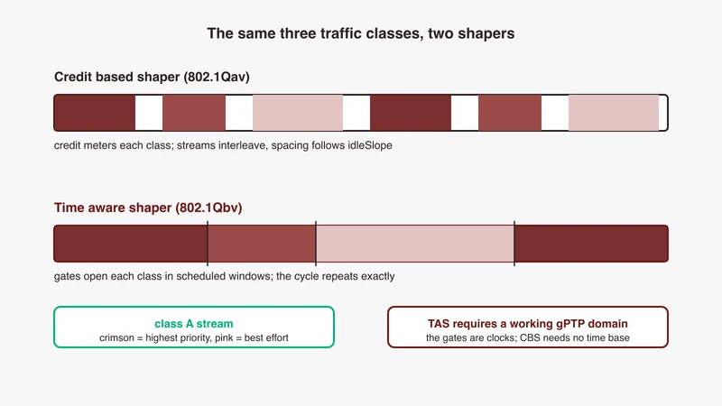
In vehicle networks, IEEE 802.1Q VLANs separate domains and services on one physical link, while the 3-bit priority code point plus a shaper, credit based (802.1Qav) or time aware (802.1Qbv), decides which frames get bandwidth and when. The priority code point only selects a queue. The shaper behind that queue is what turns a selection into a guarantee: the credit based shaper meters a class against an accumulating credit at a configured idleslope, and the time aware shaper opens and closes gates against a schedule whose start instant is expressed in a shared time base, which is why a time aware design carries a working gPTP domain as a hard dependency and a credit based design does not.
Search for VLAN and QoS design practice and you get a campus network: trunk ports, voice VLANs, a configuration guide for a building. None of it answers what a vehicle network architect is deciding: how many VLANs, mapped to what, and which shaper sits behind which priority. This is the automotive version, and it assumes the physical layer our complete guide to automotive Ethernet covers. There is now an automotive profile to anchor those decisions to: the IEEE 802.1 TSN task group lists IEEE Std 802.1DG-2025, Time-Sensitive Networking Profile for Automotive In-Vehicle Ethernet Communications, as a published standard.
What a VLAN does inside a vehicle network
Anatomy of an 802.1Q tag: TPID, PCP, DEI, VID
The tag is four bytes after the source MAC address: a 16-bit tag protocol identifier (TPID) of 0x8100 marking the frame as tagged, then a 16-bit control field carrying a 3-bit priority, a single bit and a 12-bit identifier. The Wireshark wiki notes the priority ranges 0 to 7 and the VLAN ID is 12 bits, and that the single bit was the Canonical Format Identifier, replaced by a Drop Eligible Indicator in IEEE 802.1ad and 802.1ah and adopted by 802.1Q from 2011, which is why Wireshark exposes both vlan.cfi and vlan.dei. The other two are independent: the identifier says which network the frame belongs to, the priority code point says how an egress port should treat it.
Why vehicles tag at all: domain separation, broadcast containment, security zoning
Domain separation is architectural: one backbone carries body, chassis, ADAS, infotainment and diagnostics traffic, and a flood in one must not become a fault in another, which is the intent our domain and zonal architecture explainer describes. Broadcast containment is operational: discovery, address resolution and multicast membership traffic reach every port in a VLAN, so a chatty service oriented domain kept in its own VLAN stays off links carrying a bounded latency class. Security zoning is why the regulator cares, and a VLAN boundary applies policy rather than cryptography, which our companion article on SecOC, MACsec and TLS covers.
Where tags are added and removed: ECU stack, switch port, test tap
In the ECU stack the tag comes from a VLAN interface, and the ip-link manual documents egress-qos-map as a mapping of Linux internal packet priority to the VLAN header prio field for outgoing frames, with ingress-qos-map the reverse on receive: without an egress map your internal priority never reaches the tag. At the switch port, tags are added on ingress per the port’s PVID and removed on egress where the port is untagged for that VLAN. At the test tap, the capture path itself can remove the tag, a measurement artefact covered in our capture guide.
VLAN conventions for domain and zonal architectures
VLAN per domain versus VLAN per service class, and the hybrid most projects land on
VLAN per domain gives one VID to each functional domain; it matches the organisation chart and fails at the egress port, because one domain holds both a hard-deadline control message and a bulk log upload. VLAN per service class gives one VID to each class of treatment, so the QoS configuration falls out of it, and fails at the separation argument, because a service class spans every domain.
Most programmes land on a hybrid: VLANs follow the separation boundaries, usually domains or zones, and the priority code point inside each VLAN follows the service class, so the VID answers “who may see this” and the priority code point answers “when does this go”. State which convention you chose, because a network where half the VIDs are domains and half are service classes cannot be reasoned about later.
The diagnostics VLAN, and why it is usually its own
Diagnostics gets its own VID more often than any other function: it has to work when other things are broken, it is reached from outside the vehicle, and its transfers are large and bursty. Its own VLAN buys somewhere to rate limit a flash transfer, a boundary a misconfigured tester cannot cross, and a clean answer to what the tester-facing port’s PVID should be. Our DoIP explainer covers the protocol.
Camera and SerDes payload separation
Camera links in most current vehicles are SerDes links, not Ethernet, so the Ethernet network starts at the aggregation point behind the deserialisers. Aggregated video is a sustained stream with a known rate, so its own VLAN and priority code point give a shaper a clean target.
Reserved VIDs, default VID practice, and writing the plan down
The identifier field is 12 bits and not all 4,096 values are yours: the Linux switchdev documentation states that 802.1p tagged packets, meaning VID 0, must be treated in the same way by the device as untagged packets, since the bridge does not allow manipulation of VID 0 in its database. Confirm which other values your switch reserves, then write the plan down, one row per VID: the identifier, what it separates, which ports are members, which of those are tagged and which untagged, and the PVID of each port. A plan living only in one bench switch’s running configuration gets reverse engineered under time pressure, so it belongs in version control with the rest of the network description.
The eight priorities: PCP, traffic classes and queues
PCP is a priority, not a bandwidth reservation
The priority code point selects a traffic class, the traffic class selects an egress queue, and what happens at that queue is decided by the transmission selection algorithm configured there. Configure nothing and the answer is ordering and nothing else. A requirement line saying “control traffic shall be marked priority 6” specifies a marking and no behaviour.
Mapping table: PCP value, traffic class, queue
Priority code point to traffic class mapping is switch-specific, so any table presented as the automotive assignment is really one project’s decision. What you owe your programme is your own:
| PCP | Service class in your plan | Transmission selection | Owner |
|---|---|---|---|
| 7 | Network control and time sync | strict priority | network architect |
| 6 | Hard-deadline control | time aware shaper | function owner |
| 5 | Streamed video | credit based shaper | perception owner |
| 4 | Streamed audio | credit based shaper | infotainment owner |
| 3 | Service oriented request and response | none | function owner |
| 2 | Diagnostics and flashing | none, plus a separate rate limit | diagnostics owner |
| 1 | Bulk logging | none | test owner |
| 0 | Best effort | none | default |
Note that the numeric order is not the priority order at the bottom of the range: IEEE 802.1Q’s defined traffic types place priority 1, background, below priority 0, best effort, so a plan that treats 1 as just above 0 inverts the standard’s own intent. Add a column for the traffic class each PCP lands in on each switch and fill it from the device. The service class column is illustrative, not a default to copy, and a mapping with no named owner gets changed on a bench at 11pm and never propagated.
Queues per egress port is a hardware limit, check before you design
Traffic classes are only useful if the port has queues to put them in. The tc-mqprio manual sets its own ceiling at 16 traffic classes and adds that you cannot have more classes than queues; its queues parameter maps each class onto a range of hardware queues as count@offset, and those ranges cannot overlap and must be contiguous. Ask how many egress queues each switch port type has, because eight service classes on a port with four queues will be silently collapsed; our lab switch selection guide has the rest of the purchase questions.
Priority-to-traffic-class maps differ per device, never assume
Keep the two mappings apart before reading any of this. On a host, the map parameter of these qdiscs indexes the Linux internal packet priority, not the priority code point in the tag, and egress-qos-map is what puts a priority code point on the wire; on a bridge, the priority code point to traffic class map is a switch table you have to read back from the device. One documented Linux default and one widely copied example then sit far apart. On creation, tc-mqprio creates eight traffic classes mapping priorities 0 to 7 to traffic classes 0 to 7, and priorities above 7 to traffic class 0. The map in the first two tc-taprio examples, which is not a default but is the one most configurations start from, is written map 2 2 1 0 2 2 2 2 2 2 2 2 2 2 2 2, which that manual reads as priority 3 classified as traffic class 0, priority 2 as traffic class 1 and everything else as traffic class 2, so read the installed map back on every device rather than assuming either.
Shapers compared: strict priority, CBS and TAS
Lookup table: mechanism, guarantee, inputs, dependency, use
| Mechanism | What it guarantees | Configuration inputs | Hard dependency | Typical use |
|---|---|---|---|---|
| Strict priority | Ordering only | Priority to traffic class map, queue ranges | None beyond the map | Network control, everything unshaped |
| Credit based shaper, 802.1Qav | A rate limited share of the link | idleslope, sendslope, hicredit, locredit | Port transmit rate, max frame size, max interference size | Streamed audio, video, sensor data |
| Time aware shaper, 802.1Qbv | A transmission opportunity at a stated instant | map, queues, gate masks and intervals, base-time, clockid, max-sdu | A time base shared across the schedule | Hard-deadline scheduled control |
| Frame preemption, 802.1Qbu | An express frame can interrupt a preemptable one | fp, one element per traffic class, E for express or P for preemptible | Both link partners implementing it, and a MAC Merge layer on the device | Cutting a long frame’s interference |
Strict priority and its starvation failure mode
Strict priority is what you get when you configure nothing else; the tc-mqprio manual notes that numerous Ethernet cards support the 802.1Q link strict priority transmission selection algorithm. A higher class transmits whenever it has a frame, so if it is a stream rather than a burst the lower class may never see a gap. That reads on a bench as one function working perfectly and another timing out with no error anywhere, and raising the starved traffic’s priority just moves the starvation.
Credit based shaper (802.1Qav): idleSlope and sendSlope in plain terms
The tc-cbs manual states that it implements the shaping algorithm defined by IEEE 802.1Q-2014 Section 8.6.8.2, applying a well defined rate limiting method to the traffic. idleslope is the rate of credits accumulated, in kilobits per second, when at least one packet is waiting for transmission, and packets are transmitted when credits are equal to or above zero. sendslope is the rate at which credits deplete while a transmission is occurring, a negative number of kilobits per second, given as sendslope = idleslope - port_transmit_rate. hicredit is the maximum credit that can be accumulated, in bytes, derived as max_interference_size x (idleslope / port_transmit_rate), and locredit is the minimum credit that can be reached, calculated as max_frame_size x (sendslope / port_transmit_rate).
So the shaper cannot be configured without knowing the link rate, the largest frame in the shaped class and the largest frame that can get in front of it, and the manual adds that the entire packet size counts, including headers from all layers, so a budget computed from payload will under-provision. What is absent from the list is the point: no clock, no schedule, no shared time base.
Time aware shaper (802.1Qbv): gate control lists and cycle time
The tc-taprio manual describes it as implementing a simplified version of the scheduling state machine defined by IEEE 802.1Q-2018 Section 8.6.9, a configurable sequence of gate states. Each sched-entry carries a command, S for SetGateStates; a gate mask, a bitmask where each bit is associated with a traffic class; and an interval in nanoseconds saying how long that state is held, with cycle time the sum of the intervals, base-time the instant in nanoseconds against the configured clockid at which the schedule starts, and max-sdu corresponding to the queueMaxSDU table of IEEE 802.1Q-2018. A schedule is a statement about instants, and instants mean the same thing on two devices only if they share a time base.
Frame preemption (802.1Qbu) in one paragraph
The IEEE 802.1 TSN task group lists 802.1Qbu-2016 as Amendment 26, Frame Preemption. It addresses what a schedule cannot solve alone: a long frame already transmitting when a gate opens for an express class, which preemption lets the express frame interrupt, with the remainder sent afterwards. In Linux the hooks are in the same sched-entry command field, H for Set-And-Hold-MAC and R for Set-And-Release-MAC, and it matters when your cycle is short relative to a maximum sized frame’s transmission time, and only if both link partners implement it. The per-class selection is the fp parameter in tc-mqprio and tc-taprio, an array with one element per traffic class, E for express or P for preemptible, following IEEE 802.1Q-2018 clause 6.7.2, and the manuals note that preemptible traffic classes are accepted only if the device has a MAC Merge layer configurable through ethtool.
Choosing between CBS and TAS
Decision rule by traffic class
Streamed classes go to the credit based shaper. Audio, video and sensor streams have a rate and tolerate bounded jitter, so what they need is a protected share of the link and a limit on their own burstiness, which is what idleslope and the credit mechanism express.
Hard-deadline scheduled classes go to the time aware shaper. A control message that must be on the wire inside a defined window of a repeating cycle needs a transmission opportunity at an instant, and the gate control list is the only mechanism that expresses one.
Best effort and diagnostics get no shaper and the lowest classes. Give them a queue, keep them below the shaped classes, and rate limit diagnostics separately if a flash transfer can disturb anything above it.
The test is one question: does the requirement say how much, or does it say when.
What TAS demands that CBS does not: a working gPTP domain
A time aware schedule is defined against a clock, and the tc-taprio manual is explicit that base-time is an instant expressed against the reference of clockid, and that with full offload the clockid argument must be omitted because it is implicitly the network controller’s PTP hardware clock, and therefore not necessarily synchronised with the system’s CLOCK_TAI. Two devices running schedules against unsynchronised clocks are running two unrelated schedules that happen to share a cycle time.
So a time aware design carries a dependency chain a credit based design does not: a synchronisation domain that works, which our gPTP troubleshooting article starts from, and evidence that it works to a stated bound rather than a daemon reporting locked, which is what our time sync validation article is about. The dependency runs backwards too: a schedule that leaves no open gate for the traffic class the timing frames land in stops synchronisation dead, which we wrote up in when Qbv breaks PTP.
Combined designs, and the cost of configuring both
Most vehicle networks that use a schedule at all use both mechanisms, and the cost is the consistency. Gate windows determine when the credit shaped class can transmit at all, so its effective rate is not the one you computed from idleslope alone, and max-sdu becomes load bearing because it bounds how much of a window a large frame from another class can consume.
Ingress filtering, PVID and the silent drops
Untagged frames arriving on a tagged port
The bridge manual defines the two knobs: pvid means the VLAN is considered a PVID at ingress and any untagged frames will be assigned to it, untagged means it is treated as untagged on egress. The Linux switchdev documentation states the consequences as requirements: with VLAN filtering enabled and no PVID on the ingress port, untagged and 802.1p tagged packets must be dropped; where a PVID exists they must be accepted and forwarded according to the bridge’s port membership of the PVID VLAN; and frames ingressing with a VID not programmed into the switch’s VLAN table must be dropped. With filtering disabled the bridge is strictly VLAN unaware and processes all frames as if untagged, which is why a bench that worked before someone enabled filtering can stop working at that moment.
PVID and native VLAN mismatch across a link
The failure that costs a day is two ends of one link disagreeing about which VLAN untagged frames belong to. An independent network engineer documented the enterprise version precisely: with the command that forces the native VLAN to be tagged on a trunk, every untagged ingress frame is dropped even when it matches the configured native VLAN, and the visible result was one-way connectivity, requests reaching the far switch and replies never coming back. The automotive version is the same mechanism with different labels: one end sends untagged because its port is untagged for that VLAN, the other requires a tag or assigns untagged traffic to a different PVID, both configurations pass review in isolation, and the link is dead.
The bench symptom: link up, counters incrementing on one side only
Link light on, the transmitting side’s port counters incrementing normally because transmission succeeded, the receiving side’s frame counters flat or its discard counters climbing, and nothing in either log mentioning a VLAN. That is indistinguishable from an ECU that is not sending, which is where teams spend the hours. The two-minute test is a comparison: capture at both ends and diff the VLAN column, having first ruled out the capture path as the thing removing the tag.
Where the discard counters live and how to read them
On Linux, per-VLAN visibility is a flag away: the bridge manual documents that with the statistics option the command displays per-VLAN traffic statistics. That is the output you want, because a per-port counter aggregates every VLAN and hides the one that is failing. On a managed switch, ask before you buy whether the map and the membership table can be read back rather than only written.
Q-in-Q and tag handling in test setups
802.1ad in aggregation and capture paths
Stacked tags appear in vehicle test setups more often than in vehicles, usually through aggregation: already-tagged links collected onto one path towards a capture host, with an outer tag added to keep them distinguishable. The ip-link manual documents the VLAN protocol parameter as either 802.1Q or 802.1ad. The decoding consequence is the one to internalise, and our Wireshark decoding fix list covers it: the dissector carries a preference for the 802.1QinQ Ethertype, and if the outer tag uses a different Ethertype the inner tag is never unwound and no IP, UDP or application layer is reached. Wireshark also carries an expert label for excessive nested VLAN tags, so count the layers it rendered before concluding anything.
Taps and mirror ports that strip or add a tag
A mirror port is documented as not passing VLAN tags, with the counter-argument on the same Wireshark wiki page that on many switches the mirror can be configured to carry them, so it is a configuration to prove rather than assume. An ingress mirror shows the frame as it arrived and an egress mirror shows it after the switch made its tagging decision, so the two differ exactly when you are debugging tagging.
VLAN-aware timestamping and correlation
When Ethernet frames are correlated against CAN, LIN or FlexRay traffic on a shared timeline, the VLAN is part of an Ethernet stream’s identity: two streams with identical addressing on different VLANs are different streams, and a correlation keyed only on addresses will merge them. Our multi-bus capture article covers the timeline side. Confirm the tag survives into the capture file first, because a filter on a stripped field reports an empty result rather than an error.
A lab configuration checklist
- Enumerate services and their deadlines. One row per service: what it is, its rate, and whether its requirement says how much or says when.
- Assign VIDs from the documented plan, not from the switch’s running configuration and not from whatever the last project used.
- Map PCP to queues explicitly on every port, meaning written and readable back, not inherited from a default nobody read.
- Pick a shaper per class and record why. How much goes to the credit based shaper, when goes to the time aware shaper, everything else gets neither.
- Set PVID and ingress filtering deliberately on every port, including the tester-facing port and the capture path.
- Verify with a capture before you trust the config. Confirm at both ends of a link that the VID and priority code point on the wire are the ones you configured.
- Commit the result as configuration, not as tribal knowledge. The VLAN plan and shaper derivations belong in version control with the rest of the network description.
Where GSAS fits
GSAS Micro Systems is an engineering partner to automotive teams working on in-vehicle Ethernet, and the work above sits between the architecture document and the bench. Most teams we talk to have a VLAN plan on a slide and a switch configured by whoever set the bench up, and the two have never been compared against each other.
Our applications engineers work with teams in Bengaluru, Pune, Chennai and Hyderabad on that gap: reviewing a VLAN and priority plan against what the hardware can actually express, sizing a bench whose queue count and shaper support match the design, and proving the configuration with capture evidence at both ends of the links that matter. Where a time aware schedule is in scope, that includes treating the synchronisation domain as a prerequisite to be validated rather than a checkbox. The automotive Ethernet capabilities page sets out the wider scope.
If you have a decision in front of you, whether a VLAN convention, a shaper choice for a specific class, or a bench showing link up and delivering nothing, a technical consultation is the useful first step. Request a consultation, describe the topology and the requirement, and we will start from what the sources support.
References
- tc-cbs(8) manual, iproute2: https://man7.org/linux/man-pages/man8/tc-cbs.8.html
- tc-taprio(8) manual, iproute2: https://man7.org/linux/man-pages/man8/tc-taprio.8.html
- tc-mqprio(8) manual, iproute2: https://man7.org/linux/man-pages/man8/tc-mqprio.8.html
- ip-link(8) manual, iproute2: https://man7.org/linux/man-pages/man8/ip-link.8.html
- bridge(8) manual, iproute2: https://man7.org/linux/man-pages/man8/bridge.8.html
- Linux kernel networking documentation, switchdev: https://docs.kernel.org/networking/switchdev.html
- IEEE 802.1 TSN task group standards index: https://1.ieee802.org/tsn/
- IEEE 802.1DG project page, TSN Profile for Automotive In-Vehicle Ethernet Communications: https://1.ieee802.org/tsn/802-1dg/
- IEEE 802.1Q project page, Virtual LANs and VLAN Bridges: https://www.ieee802.org/1/pages/802.1Q.html
- Wireshark display filter reference, VLAN dissector fields: https://www.wireshark.org/docs/dfref/v/vlan.html
- Wireshark wiki, VLAN: https://wiki.wireshark.org/VLAN
- Wireshark wiki, CaptureSetup/Ethernet: https://wiki.wireshark.org/CaptureSetup/Ethernet
- An independent network engineer’s writeup on tagging the native VLAN: https://blog.pierky.com/remember-the-vlan-dot1q-tag-native-command-untagged-ingress-frames-are-dropped/
Also appears in:
Building for Automotive & Mobility?
Talk to our application engineers for personalized tool recommendations.