The PicoScope 9300 Series is one of the most underestimated instruments in Pico Technology’s catalogue among Indian engineers. The category, sequential sampling oscilloscope, is niche enough that most bench engineers coming out of an Indian electronics undergraduate program have never actually operated one, even if they have heard the term. That is a missed opportunity, because the 9300 is the right tool for a set of high-value measurement problems that show up on Indian telecom physical-layer labs, Indian SoC design house SerDes bring-up benches, Indian optical transceiver characterization rigs, and Indian defence-electronics fast-pulse labs, all of which would otherwise need a Keysight DCA-X sampling scope costing several times the 9300’s entry point. For Indian engineering teams building silicon photonics test capability, 10 Gbit/s NRZ and 25G PAM4 physical-layer validation benches, or TDR-based PCB interconnect characterization, the 9300 delivers 30 GHz electrical bandwidth and 9.5 GHz optical input in a compact desktop USB form factor.
GSAS Micro Systems is an authorized Indian engineering partner for Pico Technology, and this post is for Indian signal integrity engineers, telecom physical-layer test leads, photonics researchers, SoC design-house characterization teams, and defence-electronics pulse-instrumentation engineers who want to understand what the PicoScope 9300 actually is, what it is for, and how to choose between the 9300 sequential sampling architecture and the PicoScope 9400A SXRTO real-time architecture for specific Indian use cases.
What “sequential sampling” actually means
A sequential sampling oscilloscope is architecturally different from a real-time scope. A real-time scope (like the PicoScope 6000E) captures every sample of the waveform in a single acquisition, one trigger, one continuous stream of samples at the ADC’s sample rate. A sequential sampling scope takes one sample per trigger, moves the sample point slightly on each successive trigger, and builds up a complete picture of the waveform from many repetitions.
The trade-off:
- Sequential sampling only works on repetitive signals. The waveform must look the same on every trigger (or close enough) for the reconstruction to converge. You cannot capture a one-shot event with a sequential sampling scope.
- Sequential sampling delivers much higher effective bandwidth at a much lower cost than a real-time scope of equivalent bandwidth. A 30 GHz real-time scope is a several-hundred-thousand-dollar instrument. A 30 GHz sequential sampling scope fits a bench research budget.
- Sequential sampling is the right fit for telecom physical-layer eye diagrams, because a running link transmits the same symbol pattern repeatedly and the eye diagram is literally a sequential overlay of many symbol periods.
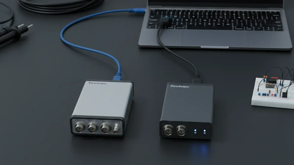
The PicoScope 9300 captures repetitive signals at equivalent-time sample rates to deliver up to 30 GHz electrical bandwidth on 2- or 4-channel configurations, in a compact USB-connected desktop form factor. Some 9300 models include a 9.5 GHz optical input for direct fiber measurement without an external optical-to-electrical (O/E) converter. Some models include an integrated 60 ps differential TDR/TDT step source for time-domain reflectometry and transmission characterization.
What the 9300 is actually for: five Indian use cases
1. Telecom physical layer: 10 Gbit/s NRZ and 25G PAM4 eye diagrams
The bread and butter application. On any running 10 Gigabit Ethernet link, 10GBASE-KR backplane, 10 Gbit/s SONET/SDH trunk, or 25G PAM4 data center link, the signal is repetitive at the symbol level and the eye diagram is the primary measurement. The PicoScope 9300 captures the eye, measures eye height and width, extracts jitter, and produces mask-pass/mask-fail results against IEEE 802.3 compliance masks, all on the same instrument.
Indian telecom physical-layer labs doing 10 Gbit/s and 25G PAM4 validation for in-house silicon, imported pluggable modules, or board-level SerDes bring-up use the 9300 as the primary bench instrument for physical-layer compliance work. The 30 GHz bandwidth is enough for 25 GBaud PAM4 rise time and overshoot measurement; the jitter decomposition features in the PicoScope 9300 software break total jitter into random and deterministic components for root-cause analysis.
2. Photonics and optical transceiver characterization
Indian optical transceiver OEMs, transceiver importers, and silicon photonics research groups at IIT and IISc (generic academic framing, not cited as customers) characterize SFP+, SFP28, QSFP28, and QSFP-DD modules by capturing the module’s transmit-side electrical output and correlating it with the specified transmit eye mask. For modules with an accessible optical output path, the 9300 models with a 9.5 GHz optical input accept fiber directly, no external O/E converter needed, and show the optical eye diagram natively.
For Indian academic photonics groups running 10 Gbit/s transmission experiments on silicon photonics chips, the 9300’s direct optical input is a practical enabler. The experimental setup is already tight on optical budget; adding an external O/E converter costs dB and introduces bandwidth roll-off. The 9300’s integrated optical input removes that loss.
3. TDR and TDT for PCB interconnect and cable characterization
Some PicoScope 9300 models include an integrated 60 ps differential step source for Time-Domain Reflectometry (TDR) and Time-Domain Transmission (TDT) measurement. TDR launches a fast step into one end of a transmission line and measures the reflections from impedance discontinuities, a bad via, a cracked trace, a connector stub, a PCB stack-up mismatch. TDT launches the step through a transmission line and measures what comes out the other end, insertion loss, rise time degradation, aggregated impedance.
For Indian SoC design house characterization teams bringing up a new board, DDR5 trace routing, PCIe Gen 5 lanes, 25 Gbit/s SerDes channel, TDR on the 9300 makes the physical channel visible before the high-speed link is brought up. This is the same workflow that would be done with a Keysight 86100 DCA-X + N1055A TDR module combination, at a significantly different price point. The 9300 is often the cost-effective answer for Indian design houses that cannot justify the DCA-X capital expense but still need the measurement capability.
4. RF pulse characterization (with a caveat: see the 9400A comparison below)
For characterizing fast pulses from radar transmitters, pulse generators, or sub-nanosecond edge sources, the 9300 works if the pulses are repetitive (running at a regular pulse repetition frequency). Indian defence-electronics RF labs (generic framing) often pair the 9300 with the PicoSource PG900 pulse generator family, in particular the sub-40 ps Tunnel Diode SKUs (PG912, PG914), where the PG900 is the fast-edge source and the 9300 is the capture instrument. This pairing delivers a compact, bench-budget fast-pulse characterization lab.
But note: if the pulse events are not repetitive, if the target signal is a one-shot glitch, an intermittent event, or a non-periodic transmitter burst, the 9300 cannot capture them. Sequential sampling requires repetition. For one-shot fast-pulse events, the PicoScope 9400A SXRTO is the right instrument.
5. Indian fiber-optic test labs and academic photonics research
The 9300 models with the 9.5 GHz optical input are the right instrument for Indian fiber-optic test labs and IIT/IISc photonics research groups running transmission experiments on silicon photonics, III-V laser diodes, and modulator development. The direct optical input saves an external O/E converter; the 30 GHz electrical bandwidth is enough for 10 Gbit/s and most 25 Gbit/s experiments; the desktop form factor fits a research bench.
PicoScope 9300 vs PicoScope 9400A: how to choose
The 9300 and the 9400A look superficially similar, both are Pico’s high-bandwidth instruments, both come in 2- or 4-channel configurations, both target signal integrity and physical-layer work. The architectures are fundamentally different, and the choice between them is driven by the nature of the signal you need to capture:
- PicoScope 9300 Series: sequential sampling. Electrical bandwidth up to 30 GHz; 9.5 GHz optical input on some models; 60 ps differential TDR/TDT source on some models; 2 or 4 channels; USB; only works on repetitive signals.
- PicoScope 9400A Series: Sampler-Extended Real-Time Oscilloscope (SXRTO). Up to 33 GHz on the 9404A-33 variant; 4-channel; 12-bit; 8 SKUs in the product line; works on non-repetitive signals; captures one-shot events.
The decision rule:
- Running link, repetitive pattern, eye diagram, jitter decomposition, compliance mask testing → 9300 is the cost-effective choice
- One-shot event, intermittent glitch, non-periodic pulse, single radar return, reset transient, debug of an infrequent fault → 9400A is the only option
Indian SoC characterization teams that do both kinds of work, running compliance eye diagrams on a stable link and debugging occasional one-shot errors, often end up owning both instruments. That is the right answer; they are complementary, not substitutes.
Hardware and software recommendation
For Indian telecom, photonics, and SoC characterization teams:
- PicoScope 9300 Series: sequential sampling, up to 30 GHz electrical, 9.5 GHz optical input, 60 ps TDR/TDT source, 2 or 4 channels, USB. The primary instrument for repetitive-signal physical-layer work.
- PicoScope 9400A: SXRTO, up to 33 GHz on the 9404A-33, 4-channel, 12-bit, 8 SKUs. The primary instrument for non-repetitive events.
- PicoSource PG900: pulse generator family with sub-40 ps Tunnel Diode SKUs (PG912, PG914), the fast-edge source for TDR reference and pulse-response characterization
- PicoVNA 108: 300 kHz to 8.5 GHz 2-port USB VNA for frequency-domain characterization of the same channels the 9300 sees in time domain
Further reading
- PicoScope 9300 Series official product page, canonical product reference
- PicoScope 9400A SXRTO product reference
- GSAS Pico Technology partner page
- PicoScope Signal Integrity, USB, PCIe, DDR, Ethernet on Indian Benches
- PicoSource AS108 and PG900 for Indian RF and Defence Labs
- PicoVNA 108 TRL Calibration and De-Embedding on Indian Benches
- PicoScope 6000E Deep Dive, High Bandwidth USB Oscilloscope
Closing: the right instrument for the right measurement class
Indian telecom physical-layer labs, SoC characterization teams, optical transceiver OEMs, defence-electronics RF benches, and silicon photonics research groups all have access to a high-bandwidth measurement need that a real-time flagship scope cannot address on typical Indian capital budgets. The PicoScope 9300 Series is the sequential sampling answer, a compact USB desktop instrument delivering up to 30 GHz electrical bandwidth, 9.5 GHz optical input, and integrated TDR/TDT at a fraction of the DCA-X price point. GSAS Micro Systems supports Indian engineering teams evaluating, purchasing, and bringing up the 9300 and the 9400A SXRTO from our offices in Bengaluru, Chennai, Hyderabad, Delhi NCR, Mumbai, and Pune: including application engineering support on repetitive-vs-non-repetitive signal classification so the right instrument lands on the right bench.
Also appears in:
Interested in Pico Technology tools?
Talk to our application engineers for personalized tool recommendations.
More from Pico Technology
View all →
How to Buy an Oscilloscope in India (2026): USB vs Benchtop, Bit Depth, Bandwidth: A Buying Guide
5 Jun · 11 min
PicoScope 5000D vs 5000E: Native 16-Bit or FlexRes? A Buyer's Guide for Indian Labs
4 Jun · 11 min
PicoScope 5000E in India: The World's First 4-Channel 16-Bit USB Oscilloscope, Explained
4 Jun · 11 min
PicoScope 7 Goes Native Arm64: Apple Silicon, Snapdragon Windows and Arm Linux Test Benches in India
4 Jun · 11 min

Emulating Processor Power for Thermal Testing: Why Constant Power
7 Oct · 7 min

CRPS and Rack Power Supply Testing: The Six Tests That Matter
7 Oct · 7 min