
In short
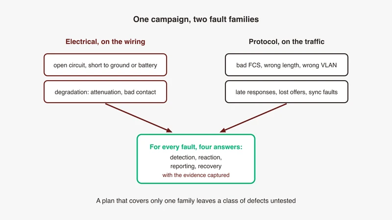
Fault injection in hardware-in-the-loop testing deliberately applies electrical faults such as open circuit, short to ground and short to battery, plus protocol faults such as malformed or mistimed frames, then verifies that the ECU detects the fault, reacts as specified, reports it accurately and recovers when the fault is removed. The two families belong in one campaign because a real network fault crosses both: a degraded pair changes link quality, and the service and diagnostic layers above then behave in ways a purely electrical test never observes. Every row of the campaign needs a fault, an injection point, an expected behaviour, an observable and the evidence you capture, and the fault insertion hardware sits in the signal path, so characterise the bench with the unit installed and idle before you trust any fault result.
Fault injection material splits in two. One half is switching hardware: relay matrices, open-load wiring, short-to-battery buses. The other half is software testing: malformed input, fuzzing, protocol robustness, written as if the wire were perfect.
A vehicle network does not fail along that line. An intermittent short changes link quality, the link logs errors before dropping, and the layers above misbehave. This article puts both families in one campaign, with the expected reaction and the observable written down per fault. If the link is not coming up at all, our 100BASE-T1 bring-up checklist works that in order; where these links sit in the architecture sets the context.
Two fault families, one test plan
Electrical faults on the wiring, protocol faults on the traffic
Electrical faults act on the conductors: open one, short two together, tie one to a supply rail, add resistance. The device under test sees them as link state, quality metrics and error counters. Protocol faults act on the bytes: a bad frame check sequence, an illegal length, an offer that never arrives, a response after the timeout. Those surface in state machines and timers.
Why covering one family leaves a class of defects untested
A pair that degrades rather than breaks keeps the link up and drops frames. An electrical-only campaign records that the link stayed up and passes; a protocol-only campaign never generates that loss pattern. Run together, the question appears: when the pair is marginal, does the ECU report a communication fault, a physical layer fault, or both?
What you are proving: detection, reaction, reporting and recovery
Four properties, and lumping them together passes on the wrong evidence. Detection, the ECU notices, at its own interfaces rather than inferred from silence. Reaction, it does the specified thing: a degraded mode, a bounded hold, a defined output state. Reporting, the diagnostic names the fault accurately, since one generic code for six faults is a finding. Recovery, it returns on its own once the fault clears.
Electrical faults on a single twisted pair
Both conductors of the pair carry signal both ways at once.
Open circuit on one conductor, and open on both
Open one conductor and the receiver loses the differential signal it was recovering; open both and you have cut the link segment. Expect the link down: our bring-up checklist records that a swapped pair is not by itself a reason for no link, because the slave corrects polarity during link-up, but continuity failures, shorts and breaks are. The case is about how fast it drops, and whether the two opens are distinguishable in the diagnostic, which is a question your requirement owns.
Short to ground and short to battery
A switching-hardware vendor’s published validation whitepaper describes inserting shorts from any wire to an external supply such as battery voltage or ground, shorts between the two wires of a pair, and partial or resistive shorts through external fault buses.
Short to battery needs planning, because it puts a supply rail onto a conductor a PHY transmitter is driving: fix the current limit and the teardown before the first run. Expect the link down again, but the diagnostic expectation is design-specific. Whether the ECU separates a short to battery from a short to ground is a requirement question, and a negative answer belongs in the record as a limitation.
Pair-to-pair short in a multi-link harness
The same whitepaper lists shorts between wires of different channels, and a single-link bench cannot produce this fault at all. One chafe in a bundle shorts a conductor of one link to a conductor of another, so two links misbehave from one cause. Which link reports first, and whether the fault handling sees a common cause, are questions the campaign owns, and a zonal layout answers them differently from a domain one; our comparison of domain and zonal architectures covers why.
Degradation rather than failure
The faults above are binary; the ones that produce field returns are not. Our guide to automotive Ethernet cables and connectors makes the point underneath: a channel built entirely from conforming parts can still sit outside the link segment limit.
Resistive shorts through a fault bus inject that deliberately, and the expected behaviour is a link that stays up and gets worse. The observables are therefore trend instruments rather than flags: the PHY’s Signal Quality Index, read relative to the maximum that PHY reports, and Mean Square Error diagnostics where exposed. Log both across the fault rather than sampling once.
What the link should do, and what the diagnostic should say
A link that is down is not automatically a link that is faulted. The OPEN Alliance publishes a sleep and wake-up specification for 100BASE-T1, so a link can be commanded to sleep by the network itself, as our article on TC10 sleep and wake-up sets out. The campaign therefore carries a negative case: sleep the link by its designed mechanism and confirm no fault is raised. No fault case surfaces that defect, because every one you wrote expected a code.
What a fault insertion unit actually does
Relay matrix versus micro-electromechanical switching
Fault insertion units are a market category rather than one product: a switching matrix puts each conductor into one of a few states, passed through, opened, tied to another conductor, or tied to a fault bus.
Electromechanical relays give a genuine metallic open and carry current, which is what a short-to-battery case wants. The same whitepaper puts the cost plainly: electromechanical relays have switching times in the millisecond range and are not designed to reliably pass signal content into the 4 to 5 GHz range, while the micro-electromechanical parts it compares them against switch in microseconds and are built for data rates up to 10 Gb/s. Where a rail is involved, current and power handling is the specification to check on the datasheet, and that is GSAS engineering guidance rather than something the whitepaper states. The same document is explicit on the mechanism: electromechanical relays introduce impedance discontinuities, stubs and parasitic capacitance that degrade signal integrity.
The unit is in your signal path
The box sits in series with a transmission line carrying both directions at once. Its insertion loss adds to your channel budget, its return loss adds reflections, and its stubs look, to the receiver, like stubs in your harness. The same whitepaper presents low insertion loss and voltage standing wave ratio on its own switching modules as what preserves the integrity of a 10GBASE-T1 signal, and notes that where rigour is required it may be necessary to measure the S-parameters of the whole fixture, then de-embed them.
Characterise the bench with the unit installed but idle
Run your reference traffic with the unit removed, logging quality metrics and error counters. Install the unit with every switch in pass-through and repeat the run. If the two differ, the unit is a term in every later result, and you have a number for it instead of an assumption. Where the link is marginal before any fault, reach for the pair itself, as our guide to scoping automotive Ethernet covers.
| Fault type | Switching element | Stresses | Measure alongside |
|---|---|---|---|
| Open, one or both conductors | Series switch per conductor | Drop detection, segment loss and restore | Link state, counters, capture |
| Short across the pair | Cross-point across the pair | Receiver under a collapsed signal | Link state, metric |
| Short to ground or battery | Current-limited fault bus | Port protection, code classification | Bus current, device state after |
| Pair-to-pair short | Cross-point between channels | Common-cause diagnosis | Both links’ diagnostics |
| Resistive or partial short | Fault bus, series element | Degradation rather than failure | Quality metric, loss rate |
Protocol and timing faults
The generator is a scripted peer, not the harness.
Frame level: bad frame check sequence, wrong length, oversize and undersize
Emit a frame whose frame check sequence does not match its contents, one below the minimum length, one above the maximum, and one whose declared length disagrees with the bytes present. Expect the receiving interface to discard and count them, and make that counter the observable, read at the device under test rather than your own.
Tagging and addressing: wrong VLAN, wrong priority, unexpected multicast
Send a tagged frame on a VLAN identifier the port is not configured for, one with a priority the deployment does not use, and one to a joined multicast group from an unexpected source. Expected behaviour here belongs to your requirement rather than a standard, because whether an unexpected tag is dropped at the port, dropped by the ECU or accepted is a decision recorded in your network design. Where nobody can point at that record, that is the finding.
Service level: malformed headers, wrong payload length, responses that never arrive
Our article on debugging SOME/IP service discovery sets out how a service goes missing: the client never received a valid offer for that instance, because discovery multicast is not reaching it or the configured unicast address is wrong.
Turn each into a case. Stop offering without an explicit stop, so the client expires the service on its time to live. Refuse a subscription. Restart the model so the reboot indication is set. Our rest bus simulation article covers each as a simulator behaviour, and each maps to a defined correct response. The response that never arrives is the most valuable: on the UDP binding, which achieves maybe reliability, the client must wait a specified timeout then signal a timeout result, so a simulator that always answers never exercises it.
Timing faults: late responses, pending handling and timeout boundaries
Our article on UDS 0x78 and P2 timeouts states the expected client behaviour: a response pending code tells the tester the ECU is still working, so the client stops the P2 timer, restarts on the longer P2 star timer and keeps waiting. Three cases follow: answer just inside the timer, just outside it, and send a pending code then answer inside the extended timer, checking the tester did not abandon a request the ECU answered late.
Time sync faults: injected asymmetry and grandmaster loss
Time synchronisation is where the families meet, because a degraded link changes path delay. Our article on validating time synchronisation makes the argument: proving 802.1AS means a bounded time error rather than a locked state, measured again during grandmaster failover, under injected path asymmetry and under load. Those three are fault injection cases already; our gPTP troubleshooting guide covers the daemon-level symptoms.
Generating these from a scripted peer rather than by hand
Scapy is the usual generator, and its documentation describes what this needs: it sends, sniffs, dissects and forges packets, it lets you put any value you want in any field you want and stack them like you want, and it names sending invalid frames among its uses. Protocol checksums and computed fields can be overridden, which covers a bad IP or UDP checksum case. A corrupt Ethernet frame check sequence is not one of them: the FCS is appended by the MAC after the frame leaves the stack, so that case needs a hardware traffic generator or a NIC that can be told to pass a supplied FCS through, not a scripted peer. The inter parameter spaces packets in time and loop repeats them, but a millisecond boundary test needs hardware-timestamped capture, not the sender.
Designing the fault campaign
The campaign table
Each row carries a fault, an injection point, an expected behaviour, an observable and the evidence captured. Where no source or requirement supports an expected behaviour, the row states the question instead. That is legitimate: it is how a campaign finds specification gaps.
The durations below are placeholders to show the shape of a row. Take the real ones from your own debounce and confirmation parameters, as the next section but one sets out.
| Fault (example duration) | Injection point | Expected behaviour | Observable | Evidence |
|---|---|---|---|---|
| Open, both conductors, 1 s | In series with the pair | Link down: breaks and continuity failures are a reason for no link | Link state, quality metric | Link state log |
| Short to ground or battery, 200 ms | Current-limited fault bus | Link down, device survives. Code classification is a requirement question | Bus current, code, functional check | Current trace, diagnostic read |
| Resistive short, 60 s | Fault bus, series element | Link stays up and degrades, frames start to be lost | Quality metric trended | Metric log, set interval |
| Pair-to-pair short, 500 ms | Cross-point between channels | Both links affected. Common-cause recognition: your requirement’s question | Both links’ diagnostics | Ordered timestamps |
| Commanded sleep, not a fault | The designed sleep mechanism | No fault raised | Link state, diagnostic read | Capture of the exchange |
| Bad frame check sequence | Traffic generator with FCS control | Discarded and counted, never seen above the MAC | Error counter at the ECU | Counter either side |
| Pending, then answer inside the extended timer | Scripted peer, or the ECU under load | The tester stops P2, restarts the longer timer, keeps waiting | Tester result, elapsed time | Timestamped capture |
| Response withheld past the timeout | Scripted peer | The client signals a timeout, not an indefinite wait | Client result code | Capture at the boundary |
| Grandmaster removed | Scripted peer holding the role | Time error stays bounded through failover, measured not reported | Measured time error | Window and topology |
| Fault removed, any row above | Switching unit or scripted peer | Link returns, the lifecycle completes again, diagnostic state clears as designed | Lifecycle stages, codes | Capture across removal |
Deriving the fault list from the design rather than a generic checklist
The faults worth bench time come from your own design: which conductors share a housing with a switched load, which links run through a connector vibration can back out, which functions have a degraded mode and therefore a reaction you can assert. As our ISO 26262 background page puts it, an integrity level is an output of the analysis for a specific item, not a property of a category of ECU. A list copied from another programme is a starting point, not a plan.
Duration and intermittency
A one second short and a ten millisecond glitch are different tests. Detection logic debounces: a fault must persist before it is confirmed, so a long fault tests detection and reporting while a short one tests the opposite requirement, that a transient is not reported, or is counted rather than confirmed. Take both durations from the design’s own debounce parameters, and add repetition as a third axis, because field connector faults look like a repeated glitch.
Recovery: remove the fault and prove the network comes back
Recovery is its own case, and it fails more often than the fault case, because a link that returns is not a network that returns. Our article on ECU testing over Ethernet makes the lifecycle argument: the stages run from link-up and address assignment through time synchronisation, service discovery and steady state to sleep, and most integration defects appear at the transitions. A fault removal is a transition, so name the stages your recovery case expects to repeat, and capture continuously across it. Automating these campaigns as part of a CI pipeline is the subject of our SDV test automation article. Our comparison of taps, mirror ports and converters covers what each method preserves; correlating captures across CAN, LIN, FlexRay and Ethernet puts a multi-bus recovery on one timeline.
Safety context, without quoting the standard
Why fault injection appears in safety programmes at all
A safety argument claims the system behaves acceptably when things go wrong, and the only direct evidence is a record of things going wrong and the system behaving. A functional test that passes proves a function works; a fault injection test proves a reaction happened, and a reaction means nothing without a stated expectation.
Read our functional-safety background pages rather than a paraphrase
Our ISO 26262 background page records that fault injection test appears among the recommended software unit verification methods in Part 6, alongside requirements-based test, interface test and resource usage evaluation. Our IEC 61508 background page sets out that the standard carries two recommendation sets, one organised by lifecycle topic and a second, more detailed set expanding particular entries, which is where dynamic analysis and testing, functional and black-box testing and failure analysis sit.
Evidence quality: what a reviewer expects a record to contain
Enough to reconstruct the run without you in the room: the fault and its injection point, the duration, the device state when it was applied, a timestamped capture spanning application and removal, the observables read at the device under test, and the expected behaviour referenced to its requirement. Then the verdict, with any limitation written as such rather than dressed as a pass. A record with no requirement behind it is an experiment, not a verification.
Automating fault campaigns
Combining rest bus simulation with fault insertion
A rest bus simulator gives the device under test a network it believes is complete, so the protocol half of this campaign becomes a change to the simulator’s behaviour rather than a new tool. Our rest bus simulation article notes that this needs a stateful, scriptable model, the top of the fidelity ladder rather than something bolted on later. It does not replace conformance, which our article on conformance above TC8 covers.
Running the campaign unattended and triaging the results
A dozen faults, three durations each and a recovery case per fault is not a manual exercise, and an expected behaviour in every row makes it machine-checkable. The ordinary requirements apply: a defined teardown, a failing case that does not leave the fault applied, and a device recoverable without a person at the bench. Then sort failures into three buckets: the ECU did not do what the requirement says, the requirement does not say, and the bench did it. The third is why the idle baseline exists.
Where GSAS fits
Bench and instrumentation review
GSAS Micro Systems is an engineering partner, and on fault injection the useful first conversation is about the bench rather than the campaign. Most disputed results we are asked about are fixture effects: switching hardware in a marginal channel, a baseline nobody recorded, or a capture that started after the interesting second.
Campaign design review
The second conversation is the campaign design, and it is a review rather than a build: which faults your design implies rather than which a generic list offers, and whether each row’s evidence traces back to a requirement. Where your campaign already covers it, that is the answer.
Our applications engineers work with teams in Bengaluru, Pune, Chennai and Hyderabad, on benches from a single link on a desk to a multi-link rig run overnight. Read the automotive Ethernet capability page for how we work, and request a consultation to have a bench and campaign reviewed against the design they prove.
References
- A switching-hardware vendor’s published multi-gigabit automotive Ethernet validation whitepaper (relay stubs and parasitic capacitance; insertion loss and standing wave ratio on 10GBASE-T1; S-parameter de-embedding; the fault list): https://www.pickeringtest.com/en-us/resources/articles-white-papers/white-papers/multi-gig-automotive-ethernet-validation
- Scapy documentation, introduction (forging packets; any value in any field; invalid frames): https://scapy.readthedocs.io/en/latest/introduction.html
- Scapy documentation, usage (
sendp;interandloop; overriding computed checksums;Dot1Q;fuzz): https://scapy.readthedocs.io/en/latest/usage.html - OPEN Alliance specification index (100BASE-T1 Sleep/Wake-up Specification): https://opensig.org/automotive-ethernet-specifications/
- GSAS Micro Systems, ISO 26262 background page (fault injection among the Part 6 unit verification methods; integrity level as an analysis output): /compliance/iso-26262
- GSAS Micro Systems, IEC 61508 background page (two recommendation sets, one by lifecycle topic and a second expanding particular entries): /compliance/iec-61508
Also appears in:
Building for Automotive & Mobility?
Talk to our application engineers for personalized tool recommendations.





