
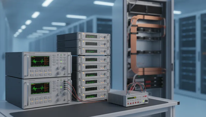
An AI rack does not fail because a model is wrong. It fails because a redundant server power module drops out under a phase sag, a busbar sags under a sudden compute load, a battery backup unit does not pick up in time, or a switch cannot survive its own port-training inrush. Long before anyone calls it AI infrastructure, it is a power delivery and thermal engineering problem, sourcing, converting, loading, cooling and monitoring, at every stage from the wall to the silicon.
That is the scope of this article, and only this article: the market scale, the memory supercycle and the full multi-partner lifecycle are covered in our AI data center field guide; this piece stays on the power, thermal, switch and optical bench.
From the wall to the core: the AI power path that has to be tested
The AI rack power path runs through six bench-validated stages: the AC feed, the server power shelf and its CRPS supplies, the 48V busbar, the battery backup unit (BBU), the DC-DC conversion stages, and the point-of-load rail, each proven on the bench before the rack reaches a data hall.
- AC feed
- Server power shelf and CRPS supplies
- 48V busbar
- Battery backup unit (BBU)
- DC-DC conversion stages
- Point-of-load rail
Trace the power path of a single AI rack from the utility feed to the accelerator die and it runs through six distinct stages, each with its own failure mode. Three-phase AC arrives at the rack’s power distribution unit and feeds a bank of hot-swappable server power shelves, commonly built around CRPS (Common Redundant Power Supply) modules, so that any single supply can fail without dropping the rack. Those shelves rectify and convert AC down to a 48V DC busbar that runs the length of the rack, the backbone every board taps into. Sitting on or near that busbar is a battery backup unit (BBU), a bank of cells that has to pick up the load within a defined ride-through window if the utility feed blips or a shelf trips. From the 48V busbar, a cascade of DC-DC conversion stages step voltage down again, first to an intermediate bus, then to the low-voltage, high-current point-of-load rails that feed the CPU, GPU or accelerator package directly.
Every stage needs its own bench validation before the rack reaches a data hall, and the rest of this article covers each one in turn.
Testing the server power shelf and CRPS supplies
A CRPS server power shelf is tested by driving its AC input with the GW Instek ASR-6000 Series AC/DC source through sag, swell and phase-loss events, then loading its DC output with PEL-5000G electronic loads to confirm every surviving module picks up its share cleanly.
A CRPS-based server power shelf is built around redundancy: several hot-swappable modules share the load so that one module can be pulled or fail without an outage. Proving that behavior means throwing at the shelf everything the utility feed and the rack’s own hot-swap events can produce, balanced and unbalanced three-phase sag, swell, momentary phase loss, and the inrush that follows a module reinsertion, then confirming every surviving module picks up its share cleanly.
GW Instek built its ASR-6000 Series for exactly this problem. (ASR-6000 Series is the family name for this product line; GSAS lists the full family on the product page linked below.) GW Instek describes the family as “particularly well-suited for next-generation AI servers and data centre power systems,” “specifically designed for high-power testing requirements, including server power modules with CRPS redundant functions.” Built on silicon carbide (SiC) technology, the ASR-6000 Series packs 4U, 6.6 kVA high power density into a single chassis, enough to program the mains-side sag, swell and phase-loss events a CRPS shelf has to survive, while also sourcing DC directly when a stage needs to be tested in isolation.
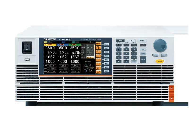
Once the AC front end has proved it can absorb a fault, the shelf’s DC output has to be loaded the way a real rack would load it. PEL-5000G high-power DC electronic loads draw realistic, dynamic current off the CRPS output rail, stepping load the way a bank of GPUs ramping into a training job would. A GPM-8320 Series digital power meter sits on the AC input to read voltage, current, power and power factor, so shelf efficiency is measured under the same conditions the load is applying, and a GDM-906x precision multimeter spot-checks individual rail voltages with laboratory-grade accuracy. The DAQ-9600 ties it together, logging every rail and every thermocouple across the whole run so a sag event and its thermal aftermath show up on the same timeline.
None of these instruments ships as a single boxed power-shelf tester. The bench above is assembled: one AC/DC source, one or more DC loads, a power meter, a precision multimeter and a data-acquisition backbone, wired around the shelf under test and automated over LAN or USB. That is what building an automated power-shelf test bench from discrete instruments actually looks like in practice, and it is the pattern the rest of this article repeats at every stage of the power path. For a closer look at the ASR-6000 family on its own, see our ASR-6000 deep dive.
How to assemble an AI power-shelf test bench
Building this bench from discrete instruments follows the same six-step sequence every time, whether the shelf under test is a CRPS server supply or a switch’s redundant PSU:
- Drive the AC front end. Connect the ASR-6000 Series AC/DC source to the shelf’s AC input to program the mains-side sag, swell and phase-loss events a CRPS shelf must survive.
- Load the DC output. Wire the PEL-5000G or PEL-5000C DC electronic loads onto the CRPS output rail and the busbar to draw realistic and dynamic current the way a populated rack would.
- Add the regenerative source for BBU and burn-in. Bring in the RBS Series regenerative bidirectional DC source to charge and discharge the battery backup unit and to return absorbed energy to the grid during long burn-in runs.
- Instrument power and rails. Place the GPM-8320 Series power meter on the AC input for efficiency, and the GDM-906x precision multimeter on individual rails for reference-grade spot checks.
- Log thermals and transients. Scan temperatures and rail voltages across the rack on the DAQ-9600, and watch transient droop and ripple on a GDS-2000A oscilloscope.
- Automate and log the run. Connect every instrument over LAN or USB, sequence the test, and log the full run so an electrical event and its thermal aftermath appear on one timeline.
Loading the 48V busbar and validating the BBU
A populated rack pulls hundreds of amps continuously off its 48V busbar, and that current has to be dumped somewhere realistic before the rack is trusted with production load. The PEL-5000C is built for that job: a dissipative DC electronic load rated from 6 kW to 24 kW per unit across 150V, 600V and 1200V models, with up to 8 units running in master/slave parallel for a 192 kW system, enough to load a fully populated busbar as one bench.
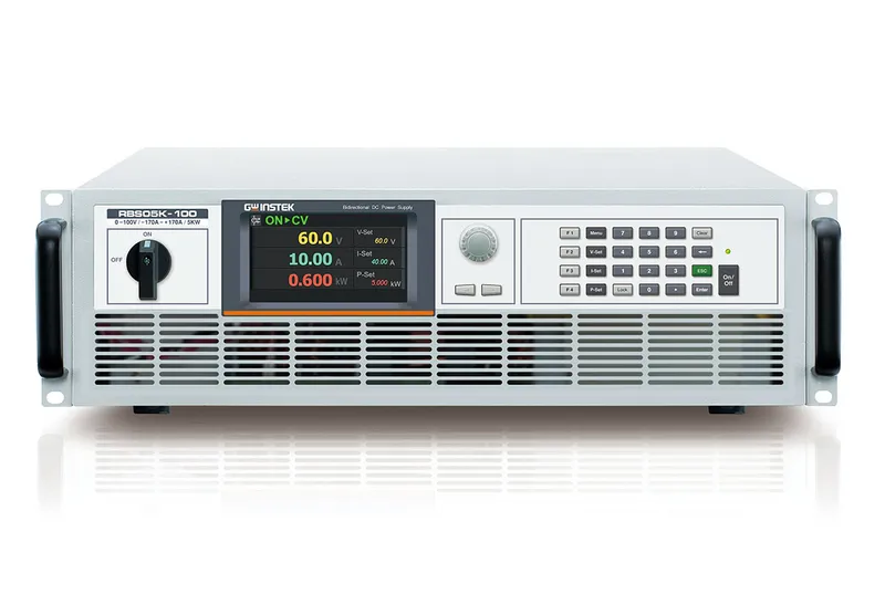
The other half of the busbar story is the battery backup unit. A BBU has to pick up the rack’s load within its ride-through window whenever the utility feed drops, and testing that behavior with a physical battery pack means destructive cycling, fire risk, and a battery that ages every time you test it. The RBS Series is the only regenerative product on this bench: a regenerative bidirectional DC source that both charges and discharges the pack from a single chassis, feeding absorbed energy back to the grid at up to 93 percent efficiency, with eight built-in battery models so BBU ride-through and hold-up behavior can be validated without a physical battery on the bench at all.
The DAQ-9600 again supplies the instrumentation layer, logging busbar rail voltage and the temperature of the connectors and bus bars through a ride-through event, since a busbar under sustained high current is as much a thermal problem as an electrical one. See our RBS deep dive for the full battery-simulation detail.
DC-DC conversion stages: from busbar to point-of-load
Between the 48V busbar and the point-of-load rail that feeds a CPU or accelerator package sit one or more DC-DC conversion stages, and those stages are judged on transient response: how far the output rail droops when the die below it steps from idle to full load in microseconds, how quickly it recovers, and how much ripple rides on top of the rail once it settles.
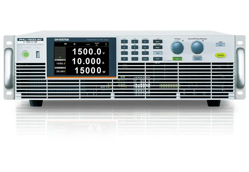
Building that test means driving the input bus at busbar voltage and stepping the output load fast enough to look like real silicon. The PHU Series provides the programmable bus source, an autoranging high-power DC source built on SiC power devices, 15 kW per 3U unit, spanning 80V to 1500V and up to 510A, so the same instrument can emulate the busbar at the correct voltage and current envelope. PEL-5000G electronic loads provide the fast dynamic step on the output side, and a GDS-2000A Series oscilloscope, with 2 GSa/s sampling and segmented memory for catching intermittent glitches, watches the rail’s transient droop and residual ripple directly. The DAQ-9600 logs the rail’s steady-state voltage and stage temperature across the same run, so a marginal converter that runs hot before it ever fails a transient test does not slip through. For help matching a GW Instek scope family to this kind of transient-capture work, see our oscilloscope selection guide.
Burn-in and reliability: proving the rack survives 24/7
AI server PSUs are burned in on the GW Instek RBS Series regenerative bidirectional DC source, which returns absorbed energy to the grid at up to 93 percent efficiency instead of dissipating it as heat, while PEL-5000G and PEL-5000C dissipative loads remain the right tool for a straightforward module soak.
Before a rack ships, its power supplies typically run a long burn-in cycle at sustained load to catch early-life failures before they happen in the field. Run that burn-in on a purely dissipative load and every watt drawn from the PSU becomes a watt of heat the test lab has to remove, on top of the electricity bill for drawing that power in the first place. The economics of burn-in matter here more than almost anywhere else on the bench, precisely because the duty cycle is so long and so continuous.
The RBS Series changes that equation for the portion of burn-in it covers: as a regenerative bidirectional DC source it returns absorbed energy to the AC grid at up to 93 percent efficiency, cutting both the electricity drawn and the cooling load a long burn-in run imposes. Where a dissipative load is the right tool, for example a straightforward PSU or module soak that does not need bidirectional charge/discharge cycling, PEL-5000G and PEL-5000C loads cover that case at their respective power levels. Either way, the DAQ-9600 does the unattended logging, its non-volatile memory and per-channel alarms are built for exactly this kind of long, walk-away run. Our regenerative versus traditional loads piece goes deeper on when each approach earns its place. For the full lineup comparison between the PEL-5000C and PEL-5000G families, see our PEL-5000G/C high-power load deep dive.
PEL-5000C vs PEL-5000G vs RBS: which load for which job
| PEL-5000C | PEL-5000G | RBS Series | |
|---|---|---|---|
| Type | Dissipative DC electronic load | Dissipative DC electronic load | Regenerative bidirectional DC source |
| Best-fit job | Bulk 48V busbar loading | Fast dynamic stepping on DC-DC and point-of-load rails | BBU charge/discharge cycling and energy-recovery burn-in |
| Power headroom | 6 kW to 24 kW per unit, up to 192 kW across 8 units in master/slave parallel | Modular, scales across modules for higher-power configurations | Up to +/-510 A per unit; parallel to 300 kW |
| Energy handling | Dissipates absorbed energy as heat | Dissipates absorbed energy as heat | Returns absorbed energy to the grid at up to 93 percent efficiency |
| Battery and BBU work | Not built for battery cycling | Not built for battery cycling | Charges and discharges the pack across 8 built-in battery models, validating ride-through without a physical battery |
Above the power shelf: 800 VDC distribution
The sections above start at the rack. Since this article was first published the industry has been standardising a stage upstream of it, and it changes what the front end of the bench has to do.
Google, Microsoft and Nvidia are working through the Open Compute Project to establish 800 VDC as an open, standardised power architecture for next-generation AI data centers. The reasoning is the one every power engineer will recognise: as racks get denser, distributing at 48 V means current and copper that stop being practical. Raising the distribution voltage cuts the current for a given power, which shrinks conductors and busbar systems and reduces distribution loss. For scale, Nvidia describes a row-level power centre supporting up to 2 MW per row.
OCP’s work treats 800 VDC as a common target interface while allowing several upstream implementations rather than mandating one: an AC-to-DC sidecar power rack retrofitted into an existing facility, a transformer-rectifier system, or a solid-state transformer architecture. OCP is explicit that 800 VDC is not a replacement for existing AC infrastructure but an additional deployment option that coexists with it. For a test engineer that flexibility is the point, because it means the stage you have to emulate depends on the customer’s topology rather than on a single reference design.
Two things follow for the bench:
- The source side needs high-voltage DC. Validating an 800 V to 54 V or 800 V to 50 V conversion stage means sourcing at the input and sinking at the output, across the full operating range, with protection and insulation behaviour exercised deliberately rather than discovered.
- The load side benefits from regeneration more than ever. A 30 kW power shelf under sustained burn-in is a lot of heat to put on a test floor. GW Instek specifies the RBS Series at a feedback efficiency of up to 93 percent when operating as a load and returning absorbed energy to the grid. That is a product specification at a given operating point rather than a guaranteed system-level figure, but the direction of the saving is the point.
Treat 30 kW as a representative module class rather than a ceiling. OCP has published an Open Rack V3 HVDC-LVDC 100 kW power shelf design specification at revision 1.0, so the power levels a bench has to reach are still moving.
The workload is now a power-quality problem
The most interesting change is not in the hardware at all. It is that a large AI training cluster behaves, electrically, like a single enormous load that switches.
Synchronous training workloads run compute-heavy and communication-heavy phases across thousands of accelerators at once. The result is recurring, correlated power swings at rack and cluster scale, and they are large enough to matter to the facility and to the utility beyond it. Work published by researchers at Microsoft, OpenAI and Nvidia reports that these oscillations fall in the 0.2 to 3 Hz band, which the authors place close to known resonant modes of grid equipment, including turbine-generator shafts and long transmission lines.
That reframes several bench measurements as power-quality measurements:
- Ramp rate, how fast cluster power rises and falls, expressed in megawatts per second at facility scale.
- Dynamic power range, the span between the floor and the peak of a workload, and how repeatable that span is across runs.
- Frequency-domain content, the oscillation spectrum rather than the time-domain waveform, because it is the spectrum that interacts with grid equipment.
Mitigations are appearing on the silicon side as well: Nvidia’s GB200 exposes power-smoothing controls including programmable ramp rates and a minimum power floor that stops the cluster dropping too far too fast. The same research reports a roughly 10.5 percent energy overhead from holding that floor at 90 percent of TDP in simulation, which is a real cost and therefore a real engineering trade-off rather than a free fix.
None of this replaces the rack-level testing in the sections above. It sits on top of it, and it means the instrumentation plan has to correlate electrical measurements with workload state and timestamps, not just record volts and amps.
Heat dissipation: multi-channel thermal validation
A high-density AI rack lives or dies on its thermals, and proving that out means measuring temperature and voltage across dozens of points simultaneously, not spot-checking one board at a time. The DAQ-9600 is built for exactly that job: a three-slot mainframe that scales to up to 120 single-ended (60 two-wire) channels and reads 14 input types, including thermocouples, RTDs and thermistors alongside voltage, current and resistance, so inlet and outlet temperature deltas, per-board hot spots and rail voltages can all be logged across a whole rack under load, on one instrument.
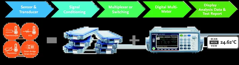
For the handful of channels where a spot reading needs laboratory-grade precision rather than DAQ-density scanning, for instance confirming a hot-spot reading against a calibration reference, a GDM-906x 6.5-digit multimeter provides that reference-grade channel alongside the DAQ-9600’s wide-channel sweep.
High-speed switches and networking gear
Top-of-rack and spine switches sit on the same power infrastructure as the compute boards, and they carry their own transient problem: when dozens of ports link-train at once after a reboot or a cable reseat, the switch’s rail current can spike hard and fast, and its power supply has to absorb that without tripping.
Validating a switch’s power rails follows the same bench pattern as the server shelf. The PHU Series sources the rail at the right voltage and current envelope, PEL-5000G loads apply the fast dynamic step that mimics a bank of ports coming up together, and the compact PEL-500 Series is well suited to smaller-scale, per-rail bench validation, including its dedicated surge test mode for boot overshoot and hot-plug transient response, a direct match for a switch that gets hot-swapped repeatedly in a rack. On the AC side, the same ASR-6000 Series that validates a CRPS server shelf validates a switch’s redundant PSU input against the same sag, swell and phase-loss conditions.
Optical transceivers on the bench
An optical transceiver draws its bias rails from the switch or NIC it plugs into, and those rails have to power up in the right sequence, land at the right voltage, and hold the laser bias steady before the transceiver’s management interface reports the module ready. Getting that sequencing wrong is a common source of link-up failures that have nothing to do with the optics themselves.
The PSW Series and PSW Multi-Channel programmable supplies apply CV/CC priority mode and adjustable slew rate to the bias rails a transceiver test fixture needs, with the PSW Multi-Channel’s programmable on/off delay sequencing built for exactly the power-up ordering a module’s supply rails require. A GDS-2000A Series oscilloscope then verifies that sequencing on the bench, capturing rail rise times, power-good timing and the low-speed, I2C-based management-sideband traffic the transceiver uses to report its status, while a GDS-3500 Series oscilloscope’s 500 MHz bandwidth, 5 GSa/s sampling and split-screen display confirm rail rise times and power-good waveform integrity on the same rails.
What these scopes do not do is measure the transceiver’s actual high-speed performance. A bench oscilloscope on this test verifies low-speed control, power-sequencing, laser-bias and management-sideband signals; it does not measure the high-speed SerDes lanes running behind an 800G port or the optical eye itself. Those measurements require SerDes-rate electrical test equipment and dedicated optical test instrumentation, outside the scope of this power-and-sequencing bench and outside what GSAS positions the GW Instek oscilloscope range for. What the bench above confirms, reliably, is that a transceiver’s supporting power and control infrastructure is sound before it ever reaches that higher-speed stage of qualification.
One GW Instek bench for the whole AI power path
The map, laid end to end: an ASR-6000 Series source and a GPM-8320 Series meter validate the AC front end and CRPS power shelf; PEL-5000C and RBS Series instruments load and cycle the 48V busbar and BBU; PHU Series and PEL-5000G instruments characterize the DC-DC conversion stages down to the point-of-load; the DAQ-9600 and GDM-906x instrument the thermals across every stage; and PSW Series and PSW Multi-Channel supplies, alongside GDS-2000A and GDS-3500 scopes, carry that same discipline out to the switch and the optical transceiver. It is one power path, and one GW Instek bench covers every stage of it.
AI power path: test area and instrument matrix
| Test area | Instruments | What it validates |
|---|---|---|
| AC front end + CRPS shelf | ASR-6000 Series, GPM-8320 Series | Mains sag, swell, phase-loss and shelf input efficiency |
| 48V busbar | PEL-5000C | Bulk busbar current loading |
| BBU | RBS Series | Charge/discharge cycling and ride-through behavior |
| DC-DC to point-of-load | PHU Series, PEL-5000G, GDS-2000A Series | Bus sourcing, dynamic load steps, transient droop and ripple |
| Burn-in | RBS Series (regenerative) or PEL-5000G / PEL-5000C (dissipative) | Long-duration soak, with or without energy recovery |
| Rack thermals | DAQ-9600, GDM-906x | Multi-channel temperature and rail voltage logging |
| Switch power rails | PHU Series, PEL-5000G, PEL-500 Series, ASR-6000 Series | Port-training inrush and redundant PSU input events |
| Optical transceiver bias/sequencing | PSW Series / PSW Multi-Channel, GDS-2000A Series / GDS-3500 Series | Bias rail sequencing and power-up timing; not 800G SerDes or optical eye measurement |
GSAS Micro Systems is an authorized GW Instek engineering partner for Karnataka, Andhra Pradesh and Telangana, which means every instrument on this bench, source, load, DAQ and scope, comes with INR invoicing, GST-compliant billing, application engineering to size and wire the bench correctly, and calibration support to keep it traceable. Whether you are qualifying a CRPS power shelf, sizing a BBU test cell, or standing up a full rack burn-in line, our application engineers in Bengaluru, Hyderabad, Chennai, Pune, Mumbai and Delhi NCR scope the configuration with you. See our full test and measurement capabilities, request a quote for the instruments above, or book a consultation to walk through your rack’s power path stage by stage.
Frequently asked questions
How is AI data center power infrastructure tested before a rack ships?
Each stage of the power path is validated on the bench: the AC feed and the server power shelf are exercised with a programmable AC/DC source, the CRPS power supplies and 48V busbar are loaded with high-power DC electronic loads, DC-DC conversion stages are characterised on a scope and DMM, and temperatures across the rack are logged on a multi-channel data acquisition system. GSAS Micro Systems supplies this full GW Instek bench in India.
Which GW Instek instruments test an AI server power shelf and CRPS PSU?
GW Instek positions its SiC-based ASR-6000 Series AC/DC source (4U, up to 6.6 kVA) for next-generation AI servers and data centre power systems, including server power modules with CRPS redundant functions. It is paired with PEL-5000G high-power DC loads to draw realistic current, a GPM power meter to measure input power and efficiency, GDM bench multimeters, and the DAQ-9600 to log the run. All are available in India from GSAS.
What validates a 48V busbar and a battery backup unit (BBU)?
The 48V busbar and CRPS output are loaded with the PEL-5000C compact DC electronic load, which scales to 192 kW across up to eight units in master/slave parallel. For the BBU, the RBS Series regenerative bidirectional DC source both charges and discharges the pack from one chassis with eight built-in battery models, so ride-through and hold-up behaviour can be validated without a physical battery. GSAS configures both in India.
How do you burn in AI server power supplies without huge electricity and cooling bills?
Traditional dissipative loads turn every watt of burn-in into heat. The GW Instek RBS Series regenerative bidirectional DC source instead returns absorbed energy to the AC grid at up to 93% efficiency, which cuts both the electricity drawn and the cooling load during long-duration burn-in, while the DAQ-9600 logs temperatures and rail voltages across the run. GSAS helps size regenerative versus dissipative loading in India.
How is heat dissipation and thermal performance validated on a high-density AI rack?
Continuous multi-channel temperature and rail telemetry is a data-acquisition job. The GW Instek DAQ-9600 is a three-slot mainframe that scales to 120 single-ended (60 two-wire) channels and reads 14 input types including thermocouples, RTDs and thermistors, so inlet and outlet deltas, per-board hot spots and rail voltages are logged across a whole rack under load. GSAS supplies and calibrates the DAQ-9600 in India.
How are high-speed switches and 800G optical transceivers tested?
High-speed switch power is validated with the PHU high-power DC source and PEL series loads with ASR sources for the switch power rails. For optical transceivers, PSW programmable supplies apply CV/CC priority mode, adjustable slew rate and, on the PSW Multi-Channel, programmable on/off delay sequencing to the bias rails, and GDS oscilloscopes verify the low-speed control, power-sequencing and management-sideband signals. GSAS scopes the right combination for optical and networking test benches in India.
What is a CRPS power supply?
CRPS stands for Common Redundant Power Supply, a hot-swappable server power module standard where several modules share a shelf so any one can fail or be pulled without dropping the rack. Validating a CRPS shelf means proving every surviving module picks up its share cleanly under mains sag, swell, phase loss and reinsertion inrush. GW Instek positions its ASR-6000 Series AC/DC source for exactly this, supplied in India by GSAS.
Regenerative or dissipative load for AI server burn-in, which should I use?
Use a dissipative load such as the PEL-5000G or PEL-5000C for a straightforward PSU or module soak, where every watt drawn becomes heat the lab must remove. Use the regenerative RBS Series when the burn-in needs bidirectional charge and discharge cycling or when long duty cycles make energy recovery worthwhile, since it returns absorbed energy to the grid at up to 93 percent efficiency. GSAS helps size regenerative versus dissipative loading in India.
How many data acquisition channels do I need for AI rack thermal validation?
It depends on how many temperature and rail points a rack exposes, but a single DAQ-9600 three-slot mainframe scales to 120 single-ended (60 two-wire) channels and reads 14 input types including thermocouples, RTDs and thermistors, so inlet and outlet deltas, per-board hot spots and rail voltages across a whole rack log on one instrument. GSAS supplies and calibrates the DAQ-9600 in India.
PEL-5000C or PEL-5000G, which DC electronic load for AI power testing?
Both are dissipative GW Instek DC electronic loads. The PEL-5000C is the compact single-channel family, 6 kW to 24 kW per unit and up to 192 kW across eight units in parallel, suited to bulk 48V busbar loading. The PEL-5000G is the modular family built for fast dynamic stepping on DC-DC and point-of-load rails. GSAS scopes the right load for your voltage, current and transient profile in India.
Sources
- GW Instek, ASR-6000 Series news release
- GW Instek, PEL-5000C product page
- GW Instek, PHU Series product page
- GW Instek, RBS Series product page
- GW Instek, DAQ-9600 product page
- GSAS Micro Systems, AI Data Centers in India: Test, Measurement & Memory Boom
- Open Compute Project, Powering the Next Era of AI: How Google, Microsoft and Nvidia Are Standardizing and Accelerating the Industry Transition to LVDC
- Nvidia, Why Scaling AI Compute Performance Requires a New Power Architecture
- Open Compute Project, Open Rack V3 HVDC-LVDC 100kW Power Shelf Design Specification, rev 1.0
- E. Choukse et al. (Microsoft, OpenAI, Nvidia), Power Stabilization for AI Training Datacenters, arXiv:2508.14318
- GSAS Micro Systems, CRPS and rack power supply testing: the six tests that matter
Also appears in:
Interested in GW Instek tools?
Talk to our application engineers for personalized tool recommendations.
More from GW Instek
View all →
Emulating Processor Power for Thermal Testing: Why Constant Power
7 Oct · 7 min

CRPS and Rack Power Supply Testing: The Six Tests That Matter
7 Oct · 7 min

GPU Power Board Testing: DC Input Verification Before Integration
7 Oct · 6 min
Servo Motor Inrush Current Testing: Method, Limits and Bench
7 Oct · 6 min

SuperTest Van Gogh 6.0: C23, C++23 and the C++20 Modules Gap
6 Oct · 7 min

AI Inside the Engineering Process: What Is Worth Automating, and What Still Needs an Engineer
21 Sept · 11 min


